

-
Posts
1,660 -
Joined
-
Last visited
-
Days Won
28
Content Type
Profiles
Forums
Downloads
Everything posted by Spector NS5 RD
-

boxer 167 battery flash after 60% & lower
Spector NS5 RD replied to EDMKEV's topic in DNA 200 and 250
If they simply replace the existing ones with the same style, my guess is you'll have the same results, maybe not immediately but down the road, taking cells in and out from the mod. More robust contacts are what's needed. Who knows, maybe they have a fix / workaround I'm not aware of. -
boxer 167 battery flash after 60% & lower
Spector NS5 RD replied to EDMKEV's topic in DNA 200 and 250
either your cells are garbage or you have poor connection somewhere between the cells and the board. since those cells work fine in your Therion, that leaves only the battery contacts. Those contacts Boxer uses are less than stellar. -
i agree with @Lowbytes. this would most likely not be the cause. OUT+ to GND = 14.xx k ohms OUT+ to BATT+ =6.xx meg ohms >>>>> not a direct short.
-
try any of these avenues?........ Tel:86-0755-27345167 Mobile:+86 15919973387 Fax:86-0755-27345050 Email:admin@hcigar.com Email: service@hcigar.com (After-Service Support) Address:2rd Floor, No. 17 Building, Hualun Technological Park, Phoenix Xingye 1 Road, Fuyong Street, Baoan District,Country/Region:China (Mainland)Province/State:GuangdongCity:Shenzhen is there a possibility the positive domed portion on the top 26650 was crushed into the cell itself creating a short, whether do to a poorly designed cell or the threaded battery cap being tightened too much? is the positive contact inside the mod spring loaded or static? the cell that vented on you, what does the top of it look like (if there is anything left of it)? can you post some high resolution pics?
-
@Brent Lavinewhat type of burl wood is that? maple? it gorgeous.
-
firstly, i do hope you are not seriously hurt. i don't own this mod, so i can't comment on the safety of using 26650 cells inside of it (IMO,i think 26650's are just not designed / up to the task for our vaping needs). this could be a design flaw in the vt75c or this could be a poorly designed, poorly performing 26650 cell. there's not enough information from the OP. best bet is to contact hcigar explain your situation and include all the pics and any info you have included in this post. one thing to add, cells that violently vent like that are usually the off-brand re-wraps, with older cell chemistry, with questionable origins. i would stay away from "Fogstar" anything from now on. the brand name alone makes me super cringey.
-
you want the analog front end IC? this is the IC - http://www.ti.com/product/BQ76925 - bq76925 VQFN (24) 6.50 mm × 4.40 mm mouser or digikey will most likely have them in stock...... you will need a hot air station to replace and SMD rework experience, not easy to reflow without proper heat shielding protecting other nearby board components from burning/melting FYI. why not just RMA the board to Evolv for replacement @Romantic?
-
Reverse polarity protection
Spector NS5 RD replied to ScaryMonkeyMan's topic in DNA 75 Color and 100 Color
the board itself has reverse polarity protection BUT not all mods have reverse cell protection (one cell input the opposite the other) built into the sled contacts. there is a difference between reverse polarity protection and reverse cell protection when dealing with dual cell parallel setups. if you accidentally put the one cell in opposite the other, creating a series circuit, it will be a series SHORT circuit (if the mod manufacturer did not implement protection against it) possibly venting one or both of the cells .- 1 reply
-
- 2
-

-
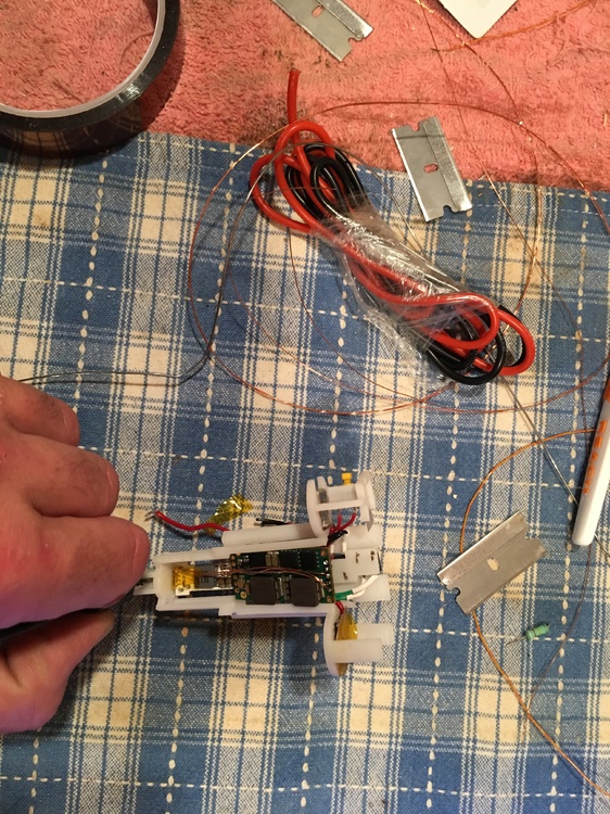
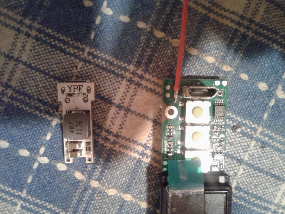
So here's my go at a DNA 60 small screen. (this was kind of a pain to do but doable. the DNA 60's 2 inductors are taller than the DNA 40's single one and with the DNA 60's addition of EScribe/data lines puts the "aggravation cherry" on top!) Got myself a Vaporflask DNA 40, a while back, from the ECF classifieds at great price. I knew the DNA 60 small screen was eventually going to come out so i figured this would be a great housing for the new board. This flask still uses the 500mA charger board that came with it originally. The charging/data board that comes with the DNA 60 is way to big to retrofit inside the flask. So I "windshield wipered" all of the charging components off of the board, with a soldering iron, except the micro USB port. I soldered tiny enamel coated wires from the back of the micro USB pinout for the data lines and thicker enamel wires for USB +5v ~ -5v. Parts...... Vaporflask DNA 40 DNA 60 SS Separate 2 amp lithium ion charger http://www.ebay.com/itm/Mini-4-2V-2A-Micro-USB-18650-Lithium-Battery-Charging-Board-LED-Charger-Module-/182275780781?_trksid=p2385738.m2548.l4275 enamel wire (found from most any circuit board choke, transformer, speaker, etc) 10k resistor (also very common on most any PCB)

-
i had a hard time finding this FW. it doesn't say anything about "small screen" in the actual SP file. even when connected to EScribe using the small screen option on the connect and download page, it had the LG screen FW. i had to just guess with the 3 SP's it listed, eventually i found it on the last try.
-
DNA75c discharge probrem.
Spector NS5 RD replied to eucalyptus.'s topic in EScribe, Software and Firmware
@eucalyptus. does the problem resolve itself if you re-install the firmware or perform a hard reset? if not, i would open a help ticket with Evolv. the board should never let the battery pack go below 2.5v. is it possible to examine the board for damaged or missing components? could you have accidentally made a mistake when soldering in board? -
my dna 75c alpinetech B box....... 2 - 4,000 mah sanyo 20700 (parallel) separate 2 amp charging module (for 3a charging total) varitube v2 30mm (horrible 510, very poor for TC. will be replacing) mamu v2 75c faceplate (shapeways)
-
@iamiam do you use drippers or have leaky tanks? it possible for ejuice to have gotten into the mod, on the PCB, creating a problem. if there is no warranty left on the device you could disassemble it and make sure the board is dry and all wiring is 100%. "shorted" doesn't always mean something is shorted. i have gotten that message with 1) poorly performing cells 2) too low of a Cell Soft Cutoff 3) poor connections from battery to contacts.
-
Replacing screen on VTBox 250
Spector NS5 RD replied to JohnHaley's topic in Installation and Assembly
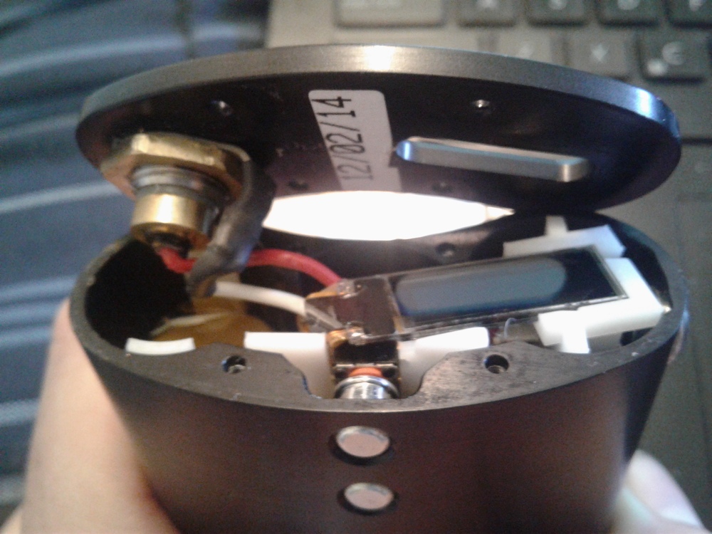
you'll need to remove the doors (unscrew) and disconnecting the lipo is important before removing the board. there are only 3 phillips head screws that hold in the board. once out (or semi-out, the 510 wires might be soldered) you can follow the DNA 200/250 datasheet for replacing the screen. (available from evolv's website). it isn't that hard, just take your time, don't lose any parts, screws or buttons, make sure ribbon connector is fully/firmly seated inside ZIF connector on board. take note of how the old screen ribbon is bent (make sure ribbon does not get pinched by fire button when re-installing board). you should do just fine. this is how ZIF latch opens and closes. don't go all HULK on it. it's very thin plastic and WILL break if abused.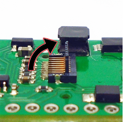
-
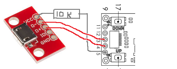
you need D- / D+ from this breakout board going to pins 13 and 14 on the DNA 60, you also need to connect VCC to USB Vdetect using a 10k ohm resistor. connect GND to any ground or batt neg point on the DNA 60. this will give you EScribe capability. make sense?
-
DNA25D Step file needed
Spector NS5 RD replied to Asfanews's topic in Manuals, Instructions, and Tutorials
if you have the step file for the DNA 40 that should work, the boards (i think) are the same dimensions...... you could also open a help ticket (link is in my signature,below) and ask Evolv staff for files. -
XvoStick DNA60, incorrectly determines the resistance
Spector NS5 RD replied to musicbox's topic in Themes and Custom Screens
to me, this sounds like an intermittent connection somewhere between the board and (including) the 510 itself. @musicbox, when you install an atomizer on DNA 60, and open EScribe's Atomizer Analyzer, is the "RAW OHMS" reading somewhat stable? a small fluctuation of 0.001 - 0.002 ohms is normal. big variances in raw ohms means a poor connection somewhere. if the wiring looks OK from board to 510, it could be where the 510 base screws into body. (i am looking at my DNA 40 Xvostick and remembered i had to disassemble and clean the entire 510 once because of high resistance readings.) basically, "check atomizer" means the board is NOT seeing the atomizer, you have to hunt down the problem. i can point you in the right direction but the rest is up to you. let us know what you find, good luck! -
Adding LED firing switch to DNA 250
Spector NS5 RD replied to bluntmoment's topic in Connectors, Components, and Accessories
what color is your LED? I'm gonna guess blue???? you need a 100 ohm resistor. red, yellow or green - 75 ohm. got a radio shack near by (?) or just go on ebay and type in "100 ohm 1/10 watt resistor" depending on your soldering skills, maybe get through hole resistors rather than SMD ones. check to see if the switch you're buying already has a resistor inside, you may not need to buy one separately. -
Adding LED firing switch to DNA 250
Spector NS5 RD replied to bluntmoment's topic in Connectors, Components, and Accessories
here in this diagram you can see where at the top right of the fire button you can tap into the LED pads. just make sure you have your polarity correct when hooking up LED. -
Hcigar Vt167 Battery Check (DNA250)
Spector NS5 RD replied to ivansn's topic in Batteries and Charging
the board inside of the mod is covered under warranty for 1 year by Evolv. open a help ticket and explain your situation. they can help you. the link is located in the bottom of my signature. -
Hcigar Vt167 Battery Check (DNA250)
Spector NS5 RD replied to ivansn's topic in Batteries and Charging
did you charge the cells inside or outside the mod? contact the vendor about a replacement since it has only been 3 days. -
this is pretty much how i handled dialing in my 133's and 167's. i'd put the the calculated Wh value in then vape down to weak battery and take note of the Wh remaining. this is with the preheat power maxed out. if i can't get the full power from the device, even for 1 second, i consider the cells dead (needs recharge). this is why 2 sony vtc5a cells only give me a little over 14.43 Wh's at max wattage of 133, calculated is 19.24. this Wh number would be higher if my preheat power was lower. so yes, i understand what you're saying. evolv's batt analyzer squeezes out every last drop of capacity. it doesn't take into account "OK, stop analyzer after test wattage can no longer be maintained." evolv is open to suggestions, there is a thread here where you can do that.
-
sounds good to me !
-

-
my dna200 doesn't charge over than 7,68V
Spector NS5 RD replied to gigxy's topic in Batteries and Charging
it is possible you may have knocked off a component during the transplant. i have seen this many times here. since you're able to remove the board, i would just RMA the board back to evolv for a replacement.


