

awsum140
-
Posts
285 -
Joined
-
Last visited
-
Days Won
11
Content Type
Profiles
Forums
Downloads
Everything posted by awsum140
-
The problem is that your Triad uses different sets of batteries, unless you leave in one set and charge with the onboard charger. Running battery analyzer might not be as productive as you might expect give that every set of batteries can, and probably does, have different capacities even within the same brand and model. I would venture that simply calculating the watt hours and entering that figure would work just as well. Normally, when running the analyzer, it is run n the 40 to 60 watt range and a few loops of wire, in the open air, will work. Another thing to look at is the soft cell cutoff setting.
-

Turnigy Nano-Tech 1.0 Discharge Profile with CSV
awsum140 replied to Daniel M's topic in Batteries and Charging
Generally, due to space limitations inside the cases, changing the battery side to an XT30 is the way to go. That also lets you trim the battery leads down to a length that will fit in without stuffing it tight. Just use caution and work with one lead at a time, a short will let out wayyyy to much of the magic smoke, and use heat shrink at the connector.- 4 replies
-
- 1
-

-
- discharge profile
- csv
- (and 5 more)
-
Since you built it yourself, maybe have a look at the board and see if there's any obvious problems around the USB connector or internally with the pins of the USB connector. If not, or if you don't want to do that, time for an RMA. It sound pretty unusual and is probably the first time I've seen that happen, but anything can, and will, happen.
-
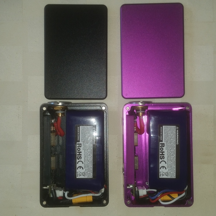
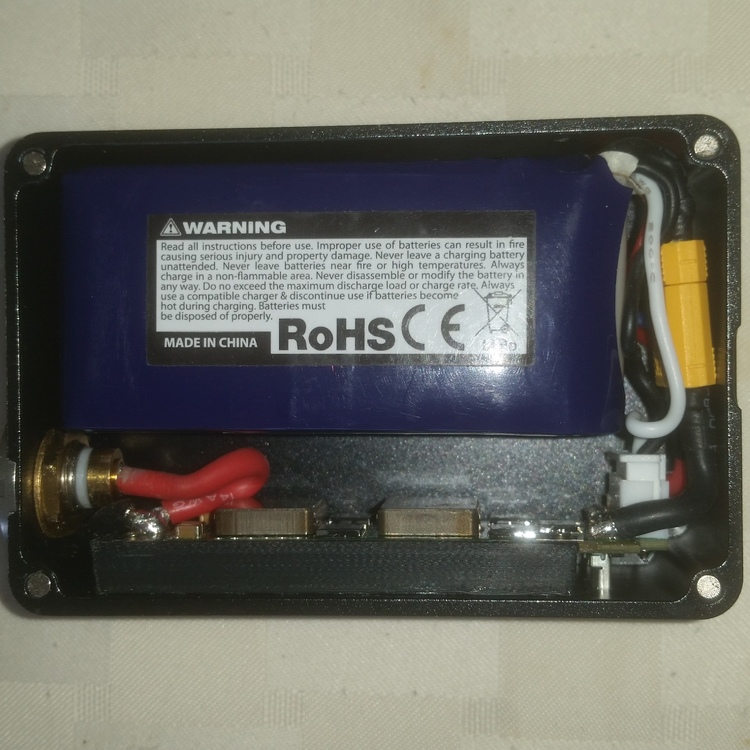
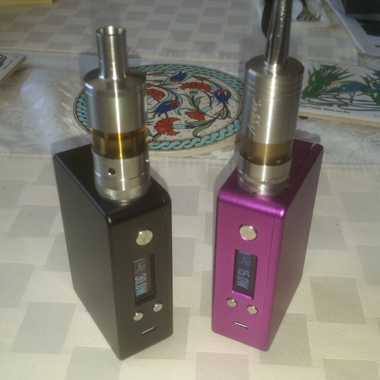
I've had the boards, DNA250s, since they came out and got the enclosures about two months after that. Finally got the pair of them done. Drip3D enclosures. They seem bead blasted then anodized and the finish is really nice and feels nice to hold, no finger prints either. I use FDV V3 510 connectors, had to use them since they've been sitting for a few years, and Nanotech 1300mah batteries. The black one is mine and has an Aromamizer V1 on it. The violet one is for the Mrs. and has a Fogger V4.1 on it. Here they are, side by side, with the covers off - And here's a closer view of the inside of mine, but they're bot the same. I compromised by mounting the board sled/screen holder with LokTite, gel, instant adhesive. The batteries are secured with Velcro, two one inch squares per battery. Normally I would have kludged some metal brackets and JB welded them into place for both the sled and battery but I wanted to get these things completed and in use. Overall, I'm happy with them but still need to run case analyzer on both of them.
-
With "cold ohms" at "?" it either isn't seeing the atomizer of you need to press the fire button once to get a reading. If it isn't seeing the atomizer, check the connection between the atomizer and the mod, after that the connection between the 510 and board inside the mod.
-
600F is not enough for stainless steel coils!
awsum140 replied to sdmf74's topic in EScribe, Software and Firmware
I really don't think the problem is the chipset or the software. The biggest problem is finding the right TCR curve for the specific wire being used. Even relatively minor changes along the curve will effect how well it vapes. That's not chipset/DNA related, it's more related to inconsistencies in the wire types and the specific run of the wire or even variations inside a small roll or wire. Stainless does seem to be more prone to this problem though. The biggest problem is that without a lab quality micro ohmmeter it becomes a "by guess and by gosh" operation and leaves you wondering just what the real temperature of the build is. -
600F is not enough for stainless steel coils!
awsum140 replied to sdmf74's topic in EScribe, Software and Firmware
Again, I'll go back to the contact problems. You've supplied more information and you're having problems with replaceable coils, not hand built coils. The major difference being the center pin connection quality. -
600F is not enough for stainless steel coils!
awsum140 replied to sdmf74's topic in EScribe, Software and Firmware
You're probably right, VB. If it was getting that hot it couldn't actually be vaped. -
600F is not enough for stainless steel coils!
awsum140 replied to sdmf74's topic in EScribe, Software and Firmware
I didn't want to go there, either, but 600F is REALLY kind of high. -
600F is not enough for stainless steel coils!
awsum140 replied to sdmf74's topic in EScribe, Software and Firmware
I would speculate that there are some settings that need to be tweaked or there are problems with the atomizers. The one that pops into mind, first, is mod resistance. At 600 degrees you should be getting a disgusting, burnt, taste loaded with things you really don't want to be inhaling. In fact, even at about 500 degrees the taste should be getting right on the edge of being bad. In terms of safety, not producing harmful by-products, you really want to stay below 470F. I have an old Big Fogger that has problems with varying resistance. It can vape well one minute and be weak to non-existent and go into temperature protection the next minute. This is a result of a poor connection at the center pin which is producing variations in resistance seen by the chip. The variation is only a hundredth of an ohm or so, but that is more than enough to effect performance dramatically. Like VB, I use 316L, mine is from Temco, with the SS profile from Evolv (stock profile) and the highest I am running is 400F. Those are single wire, 26 gauge, 6 wrap coils and are in both single and dual coil RTAs. Another thing to check is the center pins on both the atomizer(s) and mods to make certain they are clean and the spring on the center pin of the mod is working properly. -
And I thought mine was "overkill! The buss wiring is 10 gauge solid wired to an XT30 with 12 gauge silicon for convenience.
-
B+ PULLED UP AFTER SOLDERING DNA 250
awsum140 replied to bluntmoment's topic in Connectors, Components, and Accessories
Back, in ancient times, when I was in tech school that was called "the RCA method"...learn by doing. Pre-tin the wire, lots of heat with just a short time in contact, good solder and good flux will help prevent those kinds of problems. -
Battery Max sustained and peak input settings
awsum140 replied to Suitednbooted91's topic in Batteries and Charging
I think the bottom line is that the battery under normal load, think effective resistive load, won't supply more current than it is capable of. Under "dead short" or effective dead short conditions that goes out the window along with the battery and the magic smoke that makes it work. As the current demand goes up the delivered voltage will drop and the protective circuits on the DNA board will "see" that and limit power accordingly. It's amazing just how much can be packed into a chip today. -
If it's "heavy formvar" magnet wire the current rating will be higher than standard enamel coated magnet wire since it has a much higher heat rating. I wouldn't worry, too much, about silicon wire moving around inside a mod. Yes, solid wire can be neatly formed and look "nice", but silicon wire can also be "formed", sort of anyway, and doesn't really move much at all. Plus it gives you the advantage of being able to assemble without worrying as much about stressing battery connections. The motion of the 510 center pin is not all that great, but over time, could either break a solid wire or cause separation of the foil from the board depending on how the stress is transmitted by the wire. I used 12 gauge silicon to the 510 in all my DNA200 and DNA75 mods and basically had to pre-bend it into shape prior to actual final assembly. It still looks the same today as the day I built them, over a year an a half ago.
-
Sorry to hear you're having such a problem. If it's venting hot air from a battery vent I'd be extremely reluctant to use it. I have multiple 75s and 200s, all hand built, and have never experienced anything remotely like that.
-
The ratio of PG to VG in your liquid can contribute to the problem you are encountering. If there is a higher percentage of VG the liquid will get thicker in the cold which will change how well it wicks. My suggestion would be to use different profiles to compensate for the colder weather in the early morning and warmer weather in the mid day and afternoon. I'm in the northeast, New Jersey, and the temperatures are getting colder than what you are experiencing. I use liquids with a 50/50 ratio of PG/VG and they do change flavor, and vapor output, in the cold but I guess I'm used to it and don't really notice it very much.
-
It gets a little "nebulous" talking about current/voltage in series and parallel circuits because the power level is maintained by the chip in the case of a DNA or other regulated mod. In the normal world, the current would, indeed, double with a doubling of supply voltage, but the chip prevents that to maintain the power at the desired level hence the current drops by half instead.
-
The current, total circuit current, is effectively cut in half since the voltage is doubled. I'm not saying that each battery only supplies half the total current, they both supply the same amount of current but it will be half that of a single or parallel battery arrangement when the output power is the same. That's why high voltage is used for power transmission, to lower the current load and allow smaller conductors to supply higher power levels. As voltage increases, current decreases assuming the same load, output power, is maintained.
-
My comment is since the total voltage doubles, the current is cut in half for each battery. Yes, they still conduct the same amount of current but it is reduced by 50% because the voltage is increased by 100%.
-
A few people, whom I trust to be "professional", have reported that a voltage appears on the 510 connector with no atomizer on the device and the fire button not being pressed on the 75 and 200. It's not a "high" voltage and seems to max out at about .6 volts. It also seems to creep up to that .6 level over time. I am curious about the source of that voltage and its current capacity. I suspect it wouldn't be much current given the behavior, probably microamps or lower. I'm also wondering if it is designed that way for some reason or if it's just "one of those things". Any input would be welcome.
-
I'm one of the deplorable morons, too.
-
I'll leave the solder evaluation to Retird, he's got eyes like a hawk! Did you use a voltmeter to check the balance connector on the battery to make sure it is set up in the right sequence and that red is truly positive power on the main power connections? If you soldered on that ground lead to the 510 did you check for a short in it after soldering? Not trying to be a smart guy, just looking for the obvious first and I've "been there and done that" myself.
-
All I can say is that your experience is an exception, not the rule. I will also say I've had excellent customer support from Evolv, even when the failure was from my own mistakes. All of my DNA mods, 40's, 75's and 200's have been hand built by me so I've never had to deal with a third party vendor, other than myself.
-
The DNA200 draws about 30 amps at max output if I remember correctly. Assuming you don't run it that high a 20C should be fine especially considering that vaping is essentially a pulse of current rather than true continuous current.
-
If you have some spray silicon lube around, spray some on a solid surface, piece of cardboard, and use a tooth pick to put a tiny amount around the button(s) that are sticking. Just be careful to use as little as possible, it's easy to add more but too much might not be good for the board. I had a handbuilt mod that was sticking with the down button and that trick worked fine and is still working fine after a year (probably worn in by now).


