

lewisss
-
Posts
139 -
Joined
-
Last visited
Content Type
Profiles
Forums
Downloads
Everything posted by lewisss
-
Not getting a new coil promt when I switch tanks.
lewisss replied to brianvape's topic in Report a Bug
The dna200 only asks if it as a new coil if it is close to the last coil you had, (within a certain percentage) if it is a long way off it treats it automatically as a new coil -
happy christmas, but the real reason i am posting is Are you still there? Johns last post was 9th november, Brandon 30th September and James 8th December. I know you guys must be busy but it would be nice to see you back on here a bit more regularly, if only to see you are still there and still care. it would be even nicer if we had any news on forthcoming updates, status of the replacement screens and some answers to some of our questions and suggestions. ie ability to change temp rather than power on the main screen!!!!!!! Updates on the mac version, and it would be fantastic if you could let us know the breakdown of reasons for board failures on all of the chips that have been RMA'd
-
It could be this:- kanthal when heated up forms an oxide layer outside the wire, this oxide has an extremely high resistance and is extremely strong. so when current passes through the coil it cannot 'jump ' loops and the current has to follow the full route of the wire. as the oxide layer is forming an effective isulation for the wire. nickel also forms an oxide layer, but it has poor insulation properties. so if the loops of the coil touch they effectively short, hence why nickel should be used only as spaced coils. Titanium and SS fall in between these two. I have had very little luck with contact coils in SS titanium contact coils are much better as long as you heat them to a dull red first (at your own risk!) at this temp they change colour to all colours of the rainbow, I find a metallic blue works best. If you heat them any further they go white (this is the formation of titanium Dioxide) at this point throw them away .......... you have gone too far!
-
I will put my vote for this as I have on the other two threads for this request, come on can we ha have an answer from someone in evolv regarding this please
-
Sits down, gets comfortable!
-
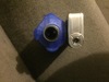
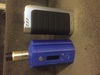
Triple 18650 next to an ipv4s
-
Does this constitute a fire risk? Cardboard mod , not easy to lose. But I do get funny looks in the street using it!

-
Absolutely agree with the service Rob at Vapegeek gives out. I had a faulty vt200 from Rob and he has either phoned me or texted me with progress of the replacement (last text was today to tell me he has received it and posted it, so I will have it tomorrow! In the interim he sent me a silicone sleeve for it foc! Service like this is extremely rare nowadays and he will get all of my future orders
-
This might be a stab in the dark but are all the balance leads the same length? I had the same issue with a 3x18650 dna I built, two of the leads were short as they were connected close to the balance port.and the other lead was the length of a battery as it had to be connected the other end. Once I remade it with equal length balance leads the issue went away!
-
very helpful, Any chance you could work out how to do it for 3x 18650?
-
Using DNA200 without the balancer connector?
lewisss replied to obicom's topic in Batteries and Charging
One way to do it would be to put a connector in the centre of the tube linked to the balance plug and insert one battery from the top and one battery from the bottom. Obviously this complicates things but it would only add the thickness of the connector to height of the mod -
[Build Log] Modifying my Lavabox 200 for a 1300mAh battery
lewisss replied to PandaSPUR's topic in DNA 200 and 250
Try Blender for 3d modelling, it's free and will have everything you need. It is a lot harder to learn than tinkercad, but it has video lessons to get you started and a decent community. -
I would be very wary of doing this. the batteries are wired in series now normally if you took any one of the batteries out of the chain there would not be a circuit made. So why is yours working like that? with 3 18650 in the dna 200 the first battery +ve goes to the B+ on the chip with 16 gauge wire the third battery -ve goes to the B- on the chip with 16 gauge wire. the only way yours is working is that by taking out one battery either the B+ or B- 16gauge wire is effectively not connected. so the current is finding another way through. where? through the balance wires which are a damn sight smaller than 16 gauge. It will work, for a while, but it wont be long before that wire overheats and could possibly cause a fire. Put up with the weight! [/QUOTE] think this has got out of hand and been misinterpreted from what i posted here!!! I did not mean that the wires in the releaux were sub standard! I meant that if Xenonram found it was working with only two batteries it means that the circuit is being made via the balance wire rather than the correctly sized Battery wire which could cause an overload if it also fired. Also I got it wrong as well as Jaquith pointed out if they are using silicon insulated wires the minimum recommended are 20 gauge apologies if this has caused any concerns
-
case analyzer: run with or without atty?
lewisss replied to mactavish's topic in EScribe, Software and Firmware
Hi Nic. Beautiful Idea A Question. Those are 1 Ohm Screw Tap Mounted Aluminum Housed Wire-wound Resistors. How did you manage to get them to read .25 ohms? My limited understanding is... when wired in parallel, they should read 4 ohms + (adding to it the resistance of the connecting wire too) total resistance. No? Method two of my hind sight thinking tells me that maybe each resistor is playing off each other. IE: one resistor is 1 ohm, put another behind it and it then becomes 1/2 (.5)ohm. Add one again, making it 3 in line wired in parallel would then, I would think, take it down to .25 and the forth one would 0 out the ohms. LOL hind sight thinking isn't working for me either. I must be missing a very important part of electrical knowledge here. So could you explain please how with four you got .25 cuz I just purchased 2 sets of these and they are on the way. Got the connector too but I'm just going to mount them onto a piece of NDF. Don't want to waste a good project box. Smile Resistors in series use the formula R1+R2+R3+R4+etc two resistors in parallel R1xR2/R1+R2 3 or more resistors use 1/{(1/R1)+(1/R2)+(1/R3)+(1/R4)+etc} so in this case it is 1/{(1/1)+(1/1)+(1/1)+(1/1)} = 1/(1+1+1+1) = 1/4 = 0.25ohms -
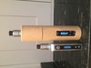
So, back in September I bought one of the first DNA200 (hcigar VT200) in the UK. I was happy with that apart from the battery. So i ordered a chip and made my first ever mod! a massive brick with a 2200 mah lipo in it! this worked perfectly for about three weeks before it blew a fuse ....... RMA1 I bought another chip while waiting for the return, put it in and 2 weeks later blew a fuse RMA2 meantime the RMA1 arrived so I put this back into the 'brick'. working perfectly. 2days later the vt200 started discharging itself once it got below 20% and getting very warm. Sent back to the retailer for replacement! RMA2 arrives last week and as the 'brick' is still working fine I am in no rush to make it up yet as I have ordered some battery holders and 3 lg3000mah brown to make a 3x18650 mod. Yesterday I had some time free so made the up the triple! Lovely build, all tested,, working perfectly, the battery analyser test was completed about 8 hours ago. 2 hours ago I went to take a puff from the 'Brick' and completely dead, nothing on the screen and no life when plugged into escribe. On testing the fuse is still intact, all the solder connections are good and the battery is at 11.1 the balance points measurements are 3.7 7.4 11.1 so that is all good. so it looks like I cannot own more than one dna device at a time! as soon as I get two, one of them fails. One thing I did notice on the latest board is that it did not have the three vias next to the B+ like the earlier boards did. I wonder if evolv can confirm this as a change
-
ok battery analyser done for LG brown 300mah batteries with the 3.09 cut off they came out at 28.97 WH so 26100 mah however these did not display the fast roll off at lower voltages that lipos do. and this was a test from their first charge. I will be re running the test once they are charged with a 3.0 volt cut off as these look like they can handle it looking at the graphs in the analyser and the battery curve is much more linear than with Lipo. I think it was john who said you could lower the soft cut off to 2.9 as the hard cut off is 2.85. (don't quote me on that!) I think this will get the reading and useful life closer to the 3000mah 33WH useful capacity forgot to put the csv in lgbrown3000mah.rtf change the .rtf to .csv and itshould work
-
Never asked if new coil regardless of wire type
lewisss replied to latexyankee's topic in DNA 200 and 250
can i ask what your profile settings are? ie preheat punch preheat wattage and final power setting? -
16gauge pvc insulated is the recommended, minimum is 18 gauge. from evolv specs. i am running the batt analyser on 3wx lg 3000mah brown as we speak so will post results when the test is done
-
It will work but it will be a brick! i have a 2200mah lipo in one I made and that is a big mod!
-
I would be very wary of doing this. the batteries are wired in series now normally if you took any one of the batteries out of the chain there would not be a circuit made. So why is yours working like that? with 3 18650 in the dna 200 the first battery +ve goes to the B+ on the chip with 16 gauge wire the third battery -ve goes to the B- on the chip with 16 gauge wire. the only way yours is working is that by taking out one battery either the B+ or B- 16gauge wire is effectively not connected. so the current is finding another way through. where? through the balance wires which are a damn sight smaller than 16 gauge. It will work, for a while, but it wont be long before that wire overheats and could possibly cause a fire. Put up with the weight!
-
I will third this suggestion. good idea. It will also start to show if the faults are build related to the vendors manufacturing process
-
as much as i disagree with the way hcigar have 'bent ' the truth about their batteries capacity, they do have a 12 month warranty. my vt200 developed a fault where it was discharging the battery on its own as soon as it got down to 20% . (using a battery analyser test done on the device set at 11.09WH 1000mah) I phoned the vendor (vapegeek in UK) and he first changed the battery and sent it back, but the fault was still there.. sent it back and he said Hcigar were good with warranty issues and a new one is on its way. Now I am not so sure that they would be so forthcoming if it had been butchered to accept a different battery. Just saying this as a warning to those of you thinking about going down this route. Evolv have been brilliant changing faulty boards either caused by the boards or caused by incorrect build practices even going to the point of repairing mods where the manufacturers have not been helpful with replacements. But Evolv is a business and I know I would be more than a bit miffed if I was constantly replacing boards that were damaged, overheated when soldering, during the mod making process and no fault of the board at all
-
Doing the mod resistance test via a dripper (doge in your example) could also add resistance due to the screw connections and the 510 connection. I have found the most accurate way of doing it would be to take that 1.5 mm copper wire and short the 510 directly or ideally if anyone knows where we can get m7 copper grub screws that would be an answer! However saying this throws up another dilemma, If we are measuring the mod resistance to ensure the coil reading is spot on., then any resistance in the tank/dripper would put that reading out.
-
haha that will teach me not to just scan the headlines!
-
here is the link, http://www.westfieldfasteners.co.uk/ScrewBolt_M.html they do cup, cone dogpoint and flat point grub screws, I ordered all 4 to try and the flat point ones work the best for me. I got m3X4mm which are longer than the originals . saying that 3 of my clones are m3 the other two are m2.5 I also got a wiha picofinish 263p hex driver https://www.wiha.com/en/produkte/screwdrivers-20728/picofinish-hex-screwdriver.html so much easier than using allen keys


