

Willy
-
Posts
91 -
Joined
-
Last visited
-
Days Won
3
Content Type
Profiles
Forums
Downloads
Everything posted by Willy
-

Project Sub-Ohm S200/Hcigar vt200 inflated battery specs?
Willy replied to VapingDragon's topic in Batteries and Charging
11.43 is what I got with that battery, I know some other's have claimed they also got in the mid 11's. I'd have to say they are over rated but your's should be better then 9.78! -
Last year I bought the Fat Daddy Vapes 510 tool, about 1/4 way down on the page, right side --> http://www.fatdaddyvapes.com/shop.html Made of stainless, you get two of them for $5, I used them for checking my mods (as well as installing 510's), just take the jam nut off before checking the resistance to make sure you bottom out in the 510. FYI, I use a copper washer between the lock down/jam nut and a 510 when installing 510's so I don't mar up a 510. Also, they don't show in the pic, there is a hex machined in the top of the tool so you can use an allen wrench. I use them to install all my 510's including the Evolv's. ETA: Here's some more pics of the tool.
-
Early Firmware and EScribe Suite Discussion Thread
Willy replied to David Campbell's topic in EScribe, Software and Firmware
Leading by example, Thank You VB -
Early Firmware and EScribe Suite Discussion Thread
Willy replied to David Campbell's topic in EScribe, Software and Firmware
Jarred, I had that happen, I finally resolved the problem by unplugging all my other usb devices, something was conflicting. I've also had problems with usb cables not working with escribe, most will charge fine but not all will work well with escribe. I bought a couple eight foot long, heavy duty, good quality cables at the local electronics shop and have never had a issue with those, it was worth the investment just in the frustration saved. -
Dna200 will not turn on with jst connector plugged in
Willy replied to seanmb's topic in Batteries and Charging
What did you use for flux? What brand is it and where did you get it? -
Hello from Mod Crate
Willy replied to Russ ModCrate's topic in Connectors, Components, and Accessories
Offering optional back halves and selling them separately would be nice, that way if someone has a mod and wants to switch to a bigger battery they could just purchase a battery and new back half, of course not just depth will allow any battery but it would allow some variance. Adding room above and below the board like Mike suggests and some width to the case will allow a much lager choice of battery's. I know a lot of folks like bigger battery's for longevity, myself I like smaller mods that fit easily in the pocket with a 800-900 mah battery because with a 1 amp charger it only takes 2- 2 1/2 hours to fully recharge and balanced. I'd also like the Evolv 510's but if you had a recess that would be nice, the Evolv 510 is tall. My 2 cents.... -
Another thing to be careful of is the flux you choose to use, NEVER use soldering paste sold in the plumbing section of hardware stores unless you damn sure it's safe to use on boards! Most of these contain Zinc Chloride flux, it is corrosive and conductive and it will continue to keep corroding. It's used in soldering copper pipes for plumbing, definitely not something you ever want to use on boards! Zinc chloride - Wikipedia, the free encyclopedia As a metallurgical flux Zinc chloride has the ability to react with metal oxides (MO) to give derivatives of the formula MZnOCl2.[32] This reaction is relevant to the utility of ZnCl2 solution as a flux for soldering â it dissolves oxide coatings exposing the clean metal surface.[32] Fluxes with ZnCl2 as an active ingredient are sometimes called "tinner's fluid". Typically this flux was prepared by dissolving zinc foil in dilute hydrochloric aciduntil the liquid ceased to evolve hydrogen; for this reason, such flux was once known as "killed spirits". Because of its corrosive nature, this flux is not suitable for situations where any residue cannot be cleaned away, such as electronic work. Guy
-
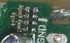
Also looks like a bead of solder on that resistor
-
Good question, when I looked closely at my board there appears to be a sleeve, a lining in the hole connecting the top and bottom pads.
-
A few things "I" would do when sending the mod back, first pull up the ser# of the board through escribe and grab a screen shot of it or take a photo of the screen. Take good photos of the mod from all sides, pack it well, make sure every opening and seam of the box is taped over then take photos of the prepped box including the shipping label. Ship it insured for full value, with tracking and signature required upon delivery. While you can't keep all bad things from happening, you can stack up documentation in case something does go south. Good luck with the exchange, I hope it goes smooth and fast. I would also refrain from complaining about someone, someone you expect to resolve an issue for you before even giving them a reasonable chance at making it right. Just saying you might be starting off on the wrong foot right out of the gate, put yourself in their shoes, would you go above and beyond to help someone if they did that to you? Good luck.
-
Post office was closed today, holiday......
-
Hello from Mod Crate
Willy replied to Russ ModCrate's topic in Connectors, Components, and Accessories
Hello Russ, So happy to see you here and asking for feedback! At some point I was planning on contacting one of you folks who make the CNC boxes to see if you would milled the boxes making them a drop in for the 510, board, buttons and screen. Seeing what others had done, stealing some ideas, coming up with some of my own, I built a couple mod's using Hammond boxes that I straighten the sides and hand filed the openings for the screen and usb port, one was a G and one an A box. More so in the A box, the mounting locations for the board and 510 is critical and every bit of space is valuable. I'd like to build some more G & A box mods, here's a few of my thoughts on them; I'd like to see the screw posts in the four corners milled away as much as possible, mill away the corners below the point where the screw ends or where the magnets are seated. The shorter the screw used for the cover the better, the more of the corner post that can be removed the better, the more you can make the remaining corner thinner the better. That corner would allow more space for wire routing and a place to tuck connectors. Myself, I rather have screws for the lid, really no reason to open these up unless it needs servicing, Torx or allen headed screws would be a nice touch! In the A I would keep the 510 centered in the top of the box, moving it closer to the board may be a problem but that all depends on the 510 used, how heavy the wire for the 510 is, how high the board is mounted and the size of the battery. I'd like to see you mill the box so we could drop the board right in the box without the use of a face plate, like my pics below. I'd like to see the the box with the board mounting holes for the screws either drilled and tapped or as you spoke of, the mounting pads part of the box, the later would be better. I'd also suggest lowering the screen opening a little to help with the issue of the ribbon cable for the screen staying clear of the fire button. Personally, if using openings in the side of the box rather then a face plate I rather see simple round buttons, I think they blend well with this style box. I like the reference case buttons, they look great on that box but out of place on a box like mine. I can make my own round buttons so I'd like to see the boxes offered with just small holes drilled for the buttons then I can open them up to match the buttons I make. Of course if you offered some round buttons with the box drilled to match it would save me time and I'd be interested! Looking forward to seeing what you come up with! -
I can understand your frustration, spending that kind of money and having a problem the day you get it but it hasn't even been 24 hours since you sent him an email. It's a Friday of a long holiday weekend, was he open today? I would give a business 48 hours, business hours, to reply before claiming they are ignoring me. Like I say it's a holiday weekend, Monday is a holiday, to be reasonable I'd wait until the end of Wednesday before claiming being ignored. I wouldn't open the case, I'd just leave it alone and wait until you hear back from him, hopefully it won't be that long. I am sincerely sorry your having a problem, I agree it does suck, don't let it ruin your holiday weekend, that won't help you at all. Put it out of your mind for now and have a good weekend. I hope you get a speedy resolution, hang in there.
-
Just a thought, wondering if you can watch the live resistance (ohm's) reading in Device Monitor when you get the shorted message? I'd be tempted to leave a usb cable connected to it, then the next time you let it set, fire up Device Monitor before you pick it up to use it and watch the reading and see what it does. My thought was, if there is a resistance change, could it be related to movement or temperature, if you can watch the live resistance when it's acting up that may steer you where to look for a problem. If your going to graph the reading make sure you set the graph time scale low otherwise a quick change might be missed.
-
Thank you John and the Evolv team for all you have done and continue to do. From someone who's life has been saved because of vaping I can't tell you how important it is to me to see these improvements and the search to make vaping as safe as possible. God Bless you for choosing a business where you can help save lives, with your talents I'm sure you could have taken other paths. I hope your greatly rewarded monetarily, blessed with a good life and with the gratification knowing the good your doing for so many now and for generations to come. A pebble dropped in a pond. Thank You!
-
Forgot to add, can you post a pic of the other side of the board including the fuse?
-
Took me a bit to find what chip you marked so I added a yellow arrow pointing it out. What's is that at the lower left mount pad where I put the blue box?

-
I think you might be surprised at the life ratings these switches have, if you asked John or Brandon they will probably give you a link to the product page of the switches used on these 200 boards. It would be interesting to compare the life ratings to the popular clicky dome tactile switches.
-
I would try to diagnose if there is a short and where the short is before any disassemble, it may tell you where issues lie in your other mods as well. If you think the board may be shorting to one of the posts I would use a DVM checking the ohms between the board and the case. If you see it's shorted, I'd wire the meter up so it's hands free and watch the meter while working on the mod, or listen if your meter can be set to "alarm for continuity" but it would be best to watch the ohms reading to see if they move at all while working on the mod and board. Once the meter is set up, one at a time, take one board mounting screw completely out while watching to see if the readings change. Once the screw is out, slighty pry the board away from the mounting post with a plastic pry tool, like those used to take cell phones and ipod's apart, these are handy little tools and can be bought from amazon for a few bucks. While there pick up some of the 3M double sided adhesive tape used to hold the screens in ipod touches, it works great for mounting screens! http://www.amazon.com/Opening-Repair-Iphone-Samsung-Galaxy/dp/B00VHT5M1A http://www.amazon.com/Ipod-Touch-Adhesive-Strip-Sticker/dp/B005EOR1L8
-
Zif socket and cable
Willy replied to Alexander Mundy's topic in Connectors, Components, and Accessories
Laguz75, Take a look at this Hakko clone from Hobby King, (some links below) I got one recently and I'm very impressed with how well it works, cost me $25 shipped to New York from their North East USA warehouse. I picked up some more tips in assorted sizes, it comes with a very fine tip which would be great for those zif's, but you'll need a larger tip for wire 20 ga and above, you can get tips from amazon. Also there is a link to a youtube video showing side by side comparison to this station and a real Hakko, the guy opens the box and shows the insides of both of them. I was quite surprised just how heavy the unit is and it looks like they made a couple improvements since that video. The temperature control is very accurate, I checked it against my Fluke meter with a Fluke thermocouple, I didn't have to adjust mine but there is an adjustment for the temp if needed. For the price, it's a pretty good station and works very well, I soldered some 12 ga wires to a 200 board and the 510 a couple days ago and had no problems getting a very impressive solder joint, key was a larger tip that wouldn't cool as soon as it touched the joint, and good no clean flux. https://www.hobbyking.com/hobbyking/store/uh_viewItem.asp?idProduct=19240 http://www.amazon.com/dp/B00KYVV9DM http://www.amazon.com/dp/B00AQARTRQ [video]https://www.youtube.com/watch?v=TP0etU7mTwU[/video] -
Bezel, that's the word I was looking for and what I meant, my mind is slipping more and more the older I get..... That wire is 16 ga silicone but will be replaced with 12. I didn't have the 12 at the time, I'll probably never push above what the 18 can handle but I have some 12 now and I just finished another mod last night, a 1590A like VapingBad's mod posted above. It was a challenge using 12 in the box, that wire ain't small! I bought a temp controlled soldering station from Hobby King, it very inexpensive but it does a nice job! I had to buy some larger soldering tips, with a bigger tip, good flux, solder and the use of helping hands I got a nice solder job even on that 12 ga wire. I dug out some scrap computer boards and practiced for a week and did a lot of reading on how to solder the right way before jumping into the deep end of the pool. I found in a lot of ways soldering is a lot like welding.
-
My other thought if you don't want to go with stand off posts, you could use J-B Weld and build up a ramp around the usb, sand it and paint the epoxy. I would whittle a dummy usb port, wrap it in tape or coat it with wax or some kind of release agent so the epoxy doesn't stick to it, get J-B Weld on or in that usb port and you'll have fun removing the board or plugging it in again. It would be nice is someone created a 3d print file, a tiny face plate to go around a protruding usb port, guys.... hint... hint... LoL
-
junianius Do you have enough room to set the board deeper and bring the usb port flush with the face? I made stand off posts, used six short self tapping screws, three from the back side of the board into the posts then three through the face of the box into the posts. The screws are 1.6 and fit nicely in the square aluminum stock, you can squeeze the stock to make the screws fit tighter if needed. I filled a notch in the back side of the jaws on some small needle nose pliers near the tip, then wrapped 28 ga kanthal around the jaw so there was a little protruding bump on each jaw, without the filed notch the wire would slip right off. For my final assembly after mock up I squeezed the flat sides of the square stock to create a tiny dent give more bite for the screws. The stock I used was from K&S Engineering stock#83010 3/32, got it from a local RC hobby shop for less the $2 You can cut it with a razor knife then final trim to length with 320 sand paper http://www.ksmetals.com/25.html NOTE: I would not trust these posts to carry B- (ground) alone through the case! After I set the board back, the back side of my buttons had a lot of clearance, I found some tiny o-rings to slip over the buttons to set them back further. They worked perfectly, giving a very slight preload on the switches, no rattle and a short and lite clicky throw.
-
"PUSH TO ARM" LoL love it! If you ever get pulled over, the cops search you car and find that can and mods with no atty's on them your probably going to get cuffed & stuffed in the back of a patrol car until the bomb squad comes and figures out what it is and clears your vehicle. Hopefully they'll figure it out and not blow your vehicle LoL! Nice job, I like it!
-
The board will stop charging the battery when it's at full charge, if you leave it plugged in for some time after it reaches full charge the screen will pull it down a little, then the board will kick back in and automatically start charging it again. You can leave it pulled in forever and it won't over charge. You could use a screen cover if you want but it's not needed, I just attached the screen right to the box using 3M double sided adhesive tape that's used to hold screen's on ipod touch, you can get it for a few bucks on amazon. http://www.amazon.com/Full-Adhesive-Apple-iPod-Touch/dp/B005ZG9X34 Tape is clear, look closely

