

-
Posts
1,660 -
Joined
-
Last visited
-
Days Won
28
3 Followers


Spector NS5 RD's Achievements
Senior Member (3/3)
135
Reputation
-
I would be curious to see how the screens ribbon cable is routed. Back when the DNA 200 was first introduced, manufacturers and modders were pinching the ribbon cable between the fire button and the onboard fire switch. Maybe this is happening, in some cases, with the newer boards/mods as well?
-
Another easy way to see if the cells are good or bad, is to fire a coil in Device Monitor while watching the each of the three cells voltages. If they plummet like a rock when firing.....time for new cells. Honestly, you can't go wrong with the Sony VTC5A cells. They're a great all around cell with a healthy CDR and decent capacity.
-
So basically the atty resistance will determine the available output voltage. The DNA 250C is a 98% energy efficient buck converter so theoretically little energy is lost during the conversion. SO.........the higher the atty resistance, the higher output voltage will be. There will always be losses and sag though.......cell quality, wiring, boARD efficiency etc etc etc Best i can explain it.
-
Max output voltage I achieved using a DNA 250C with 2 Sanyo 20070A cells with a .289 resistance = 6.43v. No where near 8.4v. here would be no way in hell there would be 0 voltage drop/sag between the cells board and atty. So you may want to re-ask your question to Evolv in the clearest, most understandable way possible.
-

Triade - Escribe shows 4 battery cells?
Spector NS5 RD replied to DanJenZen's topic in DNA 250 Color
Most likely a bug....... Me or someone here will let Evolv know about it. Thanks for bringing that to attention! -
Don't be afraid to bend the cable under the screen itself. It can handle a crease or 2, just not folding and unfolding over and over . I use my finger to tuck the ribbon under the screen then plant the screen on the board with a piece of double sided foam tape. Once and done is the goal.
-
Can you post a screen shot of Device Monitor while firing the DNA 60 Xvotstick at 15w? Make sure the battery box is checked. Let's take a look at the battery sag under load.
-
That's how they're manufactured. They're utilizing the common GND of the body/batt- to obtain the 510 GND. Perfectly OK to do as long as the 510 GND to body GND is SOLID (low resistance). TLDR......yes that's fine.
-
Replacing the motherboard
Spector NS5 RD replied to AntonioDNA250's topic in Installation and Assembly
@AntonioDNA250 It looks as if you soldered the main positive and negative leads from the lipo ONLY to the balance tap area. You also need run the main positive and negative lipo leads to the back -board main B+ and B- pads........ Do you have jumpers, from the tap to the main batt input pads, your picture isn't showing? These 2 pads need to be connected to the battery >>>>>>>>>>>>>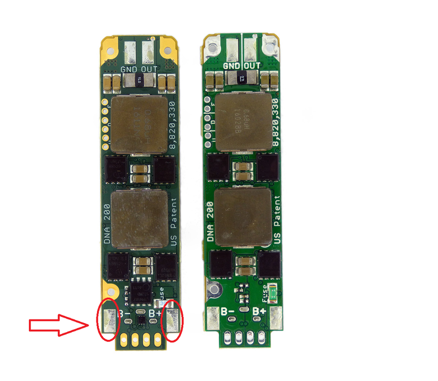
-
Replacing the motherboard
Spector NS5 RD replied to AntonioDNA250's topic in Installation and Assembly
@AntonioDNA250 Are your settings in EScribe correct? Battery settings..... 3 Cell, Lithium Polymer, Watt Hour, Cell Soft Cutoff? How about posting some good resolution pictures of your soldering. The battery wires, The Balance tap soldering -
@AMDtrucking Off topic question. when you're hauling a load, do you even need to use the clutch at all when upshifting? I have a friend who used to drive for a company (Arrow) and i would sometimes go with him on trips. I noticed once he got going, he wouldn't use the clutch. Just let off the gas and slide it into the next highest gear. Never heard any grinding or anything. How is a tractor trailer tranny able to survive with someone shifting like that? Maybe awesome well-built syncros in them trannys?
-
@AMDtrucking Are all three of those Boxer 20700 squonks authentics? (What happened to the blue one? Poor thing looks like a can of PVC glue spilled in it. lol)
-
@AMDtrucking Come to think of it, maybe you could just add a static picture of a battery gauge.... a fake gauge that always stays at 100%. I'd help you out but I'm terrible at designing theme components let alone an entire theme. I rarely change anything in the theme tab with the color boards. Hence why i use the stock Evolv theme for all my color scr boards. I'm more of a hardware guy than software. 🤪
-
@AMDtrucking There's always a solution! I can think of one, albeit a convoluted one. It would involve putting the board in Lithium ion battery mode, and tricking the balance circuit into thinking there is a physical pack present. This would involve a voltage divider (resistor) network for the balance tap area. However, I'm not sure how the board would react to a voltage that would fluctuate between 12v-14.4v . Not sure how accurate the gauge would be considering the external input voltage would essentially stay constant, for the most part. Or I could be completely wrong and missing a simple EScribe setting that resolves a non functioning battery gauge when in PSU mode. lol I can't seem to find one though.
-
TBH, i don't think the Battery gauge works when in PSU mode, regardless of how you wire anything. I haven't tried running a 250C from a PSU to test this theory but have with a monochrome 250. The battery gas gauging is generated from the analog front of the DNA board (Battery Management/Protection/Balancing IC). When in PSU mode this monolithic IC is disabled, given it's not needed when using an external PSU. In short, without that IC calculating battery capacity, the board cannot estimate a percentage. I would just delete the batt percentage field from your theme if you are going to use the board in PSU mode.


