
John
-
Posts
519 -
Joined
-
Days Won
2
Content Type
Profiles
Forums
Downloads
Everything posted by John
-
Only series. The board is step down only.
-
It definitely shouldn't do that. What firmware version? Is it running hot? It should go completely to sleep after an hour. A device monitor screenshot so we can see what it is doing would be most helpful to diagnose. And a picture of the mod.
-
Take your RDA, short across the terminals with the shortest, fattest piece of copper wire you can fit in the terminals, then fire up atomizer analyzer and read the reaistance. Put that value into the field for mod resistance. Upload settings. Done. To get the same feel as before you applied the mod resistance, expect to have to turn the power down and the temperature up.
-
If you contact Evolv's main customer support http://helpdesk.evolvapor.com/index.php?a=add they can get a new screen mailed out to you I'd imagine.
-
I know I was impressed. Are you local to us?
-
Is your cold resistance changing?
-
Did you just update to windows 10? Reinstalling Escribe might help if so. It uses .net framework 4.
-
I'll try leaving one powered up overnight with the fire button stuck and see if I can replicate problems. What firmware did it ship with? Is it always dim? If you upload settings, does the "UPLOAD SETTINGS" message appear on the screen? If so, does it appear dim or bright?
-
If the fire button was stuck down, is your battery very discharged? Can you post a screenshot of device monitor showing your cell voltages?
-
Okay... Mod resistance... First, let's look at the power controlled case only. Then we'll extend that to temperature protection. From the output of the board, there are several resistances in series that make up the load. First you have the wires running to the connector. Then you have the connector body itself. Then you have the interface between the connector and the atomizer. Then you have the atomizer body, then the connection between the atomizer and the coil. Then and only then do you actually get to the coil. All these elements have some resistance, and resistances in series add up. So, you might have Output wires: .002 ohm Connector body: .001 ohm Connector contact resistance: .002 ohm Atomizer body: .003 ohm Atomizer contact resistance: .002 ohm Coil: .10 ohm So the total resistance would be .108 However, we really only care about the heating power coming out of the coil, not the power being wasted in the wires or the connector. So to get 100 watts out of the coil, we need I^2*.10 ohm = 100 watts. So we need 31.6 amps of current to get a true 100 watts out of the coil. However, to get that 100 watts at the coil, we need to have the board put out more power, to account for the losses through all the stuff that isn't coils. We know we need 31.6 amps, so the total power we have to put out in this case is 31.6^2*.108, or 108 watts. So in this case, power controlled only, we need to put out an extra 8 watts to get our 100 out. If your mod resistance is correct, the DNA will handle this automatically. And yes, this means that in certain circumstances the board will be putting out significantly more than 200 watts. That's all good from a power standpoint (except that we have to make a board capable of more like 250 watts total output) but in temperature mode, it is a bit more nuanced. With temperature protection, we're looking for a rise in resistance relative to the known cold resistance. With mod resistance, we assume that the mod resistance isn't heated meaningfully. With nickel 200, a doubling of resistance corresponds to about 412 degrees. So if we have a mod resistance of .008 and a cold coil resistance of .10, for a total resistance of .108, the following happens: If we have a 0.0 mod resistance setting, it will assume the entire cold resistance is the coil. So for a temperature setting of 412 degrees, it will have a limit resistance of .216 ohms. However, we know in this case that .008 of that isn't the coil. We'll further assume that everything is well constructed and massive enough to not heat up much in operation. That means that our limit resistance's .216 ohms is really .208 ohms at the coil and still .008 ohms in the non-coil stuff. So for a setting of 412F, you are really getting a coil temperature of 430F. With a proper mod resistance setting, it will only be looking for a rise in resistance of the actual coil. So a setting of 412 will actually be 412. So, the temperature you are getting is closer to the temperature you have set with the mod resistance on. Unfortunately, it is more accurate in a "weaker, cooler vape" direction. To get the same experience as one would have had with a 412 degree setting without mod resistance, you would have to turn the temperature limit up to what you were actually getting before, in this specific case 430 degrees. Hope that makes sense.
-

Suggestion: Finer Temperature Adjustments
John replied to Pig's topic in EScribe, Software and Firmware
Don't worry, these will happen eventually...
-
Are you 100% certain that it is all the way connected? It is easy enough to pull the flex cable partway out of the housing as you install things. I've done it myself any number of times. If you have a large screen DNA 40 around, you could try swapping the screens to see if the screen or cable took damage. I've also broken any number of screens and cables over the years. We'll add a debug setting to the next escribe to have it able to display if the screen is disconnected or having communication issues.
-
Screen not working correctly. Mod still working fine?
John replied to plcockrell's topic in Report a Bug
To clarify, there is a minor bug, but the bug is that on powerup if you are in stealth mode, it should display "stealth mode" after the startup screens so you know what it is doing. The 200 isn't doing that properly at the moment, but it will with the next firmware update. -
Dogmods, what were you doing when the fuses popped? Can you post the serial numbers of the boards, or when they were made?
-
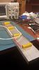
4 one ohm coils would work quite well. This is my battery analyzer test setup. It is somewhat... larger... than strictly speaking necessary (it will handle 200 watts continually) and it is permanently soldered to a test board (but I have thousands of those)
-
Screen not working correctly. Mod still working fine?
John replied to plcockrell's topic in Report a Bug
Well... We replaced plcockrell's board so we could diagnose the problem... It was in stealth mode. I guess that's a relief. How it got into stealth mode may well be a question for the ages, but I should have checked it first. We're going to add something to device monitor that tells you your mode and settings, so we can see what state the device is in in real time. That should at least prevent this issue. -
Exactly. You tap the battery tray.
-
Early Firmware and EScribe Suite Discussion Thread
John replied to David Campbell's topic in EScribe, Software and Firmware
Not so much a bug as just stopping at nice, round numbers. You really don't want to be running at 300C either. -
Battery life on the Fully Max 900 battery running at 100-120
John replied to scoopy's topic in Batteries and Charging
Scoopy if you are getting half a day from 2 Samsung INRs then you definitely want to be using something with a 2200 mah pack. Also, damn, that is a lot of vapor. -
Battery life on the Fully Max 900 battery running at 100-120
John replied to scoopy's topic in Batteries and Charging
2 VTC5s will get you a realistic 16 watt hours, so you would want a 1500 or 1800 mah 3s pack. -
Sure. Make sure it is really big and don't use nickel for this one. You want a constant resistance.
-
Sure, I will throw up a picture of my setup. Mine is overkill, because it will sink 200w continuously, but you will get the idea. For battery analyzer it doesn't matter whether how good your setup is, as long as the connections are reliable and the resistors can take the heat. All it needs is somewhere for the energy to go.
-
Battery life on the Fully Max 900 battery running at 100-120
John replied to scoopy's topic in Batteries and Charging
How long does your current device go in your usage, and what batteries does you run now? If we know that we can calculate exactly. The DNA 200 will put out exactly what it is set for, which is not the case with some other boards, but if they are really putting out, say, 90W to get the vape you like, and you set the 200 to 90W, the run time will be largely the same, with maybe a slight advantage to the 200 because it is stupid efficient. If we know what your present batteries are and we know how long your present mod runs, we can say pretty exactly how long the fullymax will go, or any other. Rule of thumb, though, the 900 goes a whole day for a 50-60 watt Atlantis user and a half day for someone with a 100 wattish, dual coil dripper. -
No, you have to run taps to the battery. Why destroy batteries to save two minutes of wiring?
-
Ah ha. You do have a popped fuse. What's happening is your device is powering directly from the USB port as a pass-through. It reads the battery voltage just fine because the battery and the taps are just fine. And obviously the board is functional other than the fuse. The question is, what is it about the Opus that makes it eat fuses? When you heard the pop, was it mid-puff? The beginning of a puff? Wake from leaving it along for hours? Just removed from charging? Did anything interesting happen to it physically beforehand? Also, without the fuse intact,don't leave it on charge or USB for extended periods of time, or the board will get warm, because it will be trying to charge batteries it can't get power to, so the whole charge power will be burned up as heat.

