

JTree
-
Posts
57 -
Joined
-
Last visited
Content Type
Profiles
Forums
Downloads
Everything posted by JTree
-
Thanks yall. I have a stack of screens here. I'm going to go through them to see which ones are good and which ones are bad and rebuild these two mods. I'll use some double sided foamed ribbon I have laying around and hope for the best. Building in these enclosures is nice, not having to solder a ground, no need for a 3d board mount, ect, but I find it frustrating that I can not *see* that the ribbon is in the right place once I screw the board down. These may be the only 2 mods i build in these enclosures due to that fact. I'd rather go through the additional trouble of additional soldering, drilling, and parts acquisition so that I don't have to redo work because there was no way to confirm one of the most fragile pieces in the build is destined to fail in a few short days/hours. Really going to miss working with them, though. Perhaps someone will come up with a 3d solution on the enclosures for the c boards, but I doubt that there will be innovation at this point. If it were going to happen, it would have already.
-
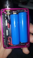
Ok so I know I am late to the party building in the concept syle enclosures, but here we are. So I'm building in a silo enclosure. Twice now I have installed the board and screen in such a way as to pinch the ribbon between the actuator and the fire button. What kind of oragami have yall used to keep the ribbon out of the way?
-
Anybody? Anybody? Bueller? Correct me if I am wrong, but doesn't usb have 4 carriers, 2 for data, 2 for power? I'm guessing that the current would have to be incoming before the switch telling the logic, "Hey, I've got power, time to give that 3 cell some of dat sweet sweet amp." I am looking at the traces and I have a guess of where a qi reciever would need to go, but I'd rather someone in the know que me in than guess on my own.
-
I've had no issues. On the 4 large pads, I bend the braided carrier I am using to give me a nice flat piece the same length of the solder pad, flux and tin the wire (no longer as malleable. Then press wire to pad and put the iron on top of the carrier. It melts right into it making a good joint. If it helps, I'm running my iron pretty hot and using a chisel tip for the large pad joints.
-
DNA200 2 x 18650 Not Registering Cell 1
JTree replied to ibanezcollector's topic in Installation and Assembly
Looking at the pictures, that contact at the bottom right....that guy looks like it might give you issues. Also, where are the actual power wires? I honestly don't know if the board using the power wires when reading the different cells (I doubt it), but I'd also try hooking up the juice before reaching out to evolv. -
DNA200 2 x 18650 Not Registering Cell 1
JTree replied to ibanezcollector's topic in Installation and Assembly
Personally, the first thing I would check is to make crazy sure the tabs on the sled were making fantastic contact with the batteries. I can not tell you how many battery sled tabs have been off center enough to rest on the flame jacket of the battery instead of the actual posts. Next, I would look for cold joints on the tabs. Not as likely in my experience, but hey, anything is possible, right? Next, look at the solder joints on the board. Still, not likely you fubbed it, but just make sure. I've had a few weird board failures switching boards around, so if all else fails, reach out to evolve. -
Yeah, I know its kind of gimmicky, but I'm considering trying to incorporate wireless charging on my next build. Where would I wire in the reciever?
-
One screw should be enough, but 2 would be pleasing to my aesthetics. No real reason to drill more holes in the 510. I'm sure I'll be able to find an Allen head machine screw that will fit the existing holes nicely. If not I'll modify the existing holes to accomdate the head. I'll post pics when I'm able to focus on this build. It's going to have me running to a fastener shop I imagine....monday seems likely.
-
Thanks for the reply. Interesting. Well I don't have a spanner wrench small enough to fit those holes, but I am totally going to use those holes to put some screws through to keep it from backing out, LOL. It never matters how much I torque a 510 through a typical aluminum enclosure or whether I put a backup nut on the bottom, they always seem to back out one day. Of course, I'm rough on things. I've considered thread lock, but I'm not willing to go the chemical solution yet.
-
B+ PULLED UP AFTER SOLDERING DNA 250
JTree replied to bluntmoment's topic in Connectors, Components, and Accessories
After soldering a few of these, my favorite method is: 1) if the wire needs to be bent to be happy in the enclosure, bent it before tining. Use flux. 2) the tab on the board has quite a bit of solder already, but go ahead and add a little more before even putting the tined wire against it. 3) put the tined wire against the tab and put your iron on top of the wire and press down a smidge. It will sink in to the solder, remove iron and wait like 5 seconds before releasing the wire. 4) smile at your perfect joint and tell it how lovely it's soldery perfection is. -
What are you guys using for the anti spin screws? My calipers aren't small enough to measure the recess and hole.
-
Without a finish, won'the the magnets start corroding almost immediately? My last set did, but maybe that was the remnants of the finish that corroded.The hair line crack doesn't offend me much. TBH, I would be more worried about it if I wasn'the already planning my next build. I think I'll order a battery this week
-
Also, I have no idea why my epoxy didn'the set completely after 10 hours, but I thought they were good, removed the clamps and they crept....argivating. i'm thinking about drilling tiny holes to eliminate the hydraulic effect next time. I used magnets on the reverse side of the door and those stayed in fine and hardened like they were suppose to.
-
Yeah it's a fat daddy v4....I'd stay way from the v5s. The v4s are easy to work with. If you 2 tone yours let me know how it works out. I'very been considering playing around with home anodizing.
-
You'll note that I over compensated with the new wire lol
-
-
Hey man, thanks for breaking the bill of that hat in. I'll be taking that from you now, as I've earned the wearing of it for a time. Ok, so this morning my build finally went nuclear and so I was of the same opinion. "I'may going in with a different, modified sled and I'm going to make this work." The battery monitor was oscillating between full and empty, and I was getting an intermittent "imbalanced" message. I started tearing stuff apart. Thankfully I never soldered the sled in (no real need to IMO, as it wants to sit right and battery swaps don'the make it move even a little). Lo and behold, as soon as I unmounted the board and pulled the sled out, the wire I had soldered from the positive to the balance tab broke right off....I had apparently gotten a little agressive when striping it and damaged most of the filaments in the core. Soldered in a new wire, screwed the board down, and my wife is back on track sacking down my juice supply.
-
I ended up modifying the taps quite a bit. On the back side I trimmed them to provide more clearance from the case and on the positive side I put a dab of solder to help get a good connection. I'll check out the show me thread for that battery. Lol I hate going to that thread because every time I go there I end up with the modding fever, planning a new build before I even get done with the one I'may doing. It really doesn'the help that I have extra components just laying around ready to be used. I've totes already started planning my next build. Think my next one will be in a g+ with a 1300 lipo I have left over from a previous build. I'll use external components for all the switches and seal the round usb hole with a silicone flanged thread protector. It'll be basically waterproof if I RTV the lid.
-
I see you even swapped the contacts around where the negative is in the upper right to try to get around the issue I am having.....this just solidifies my conviction of going good lipo. Aaaaaaaaand I'm off to hobbyking to look at batteries.
-
I just got done with my first p+ build with a 250 chip. I used the same sled and mount as you did. I'm getting really good at soldering these things up.....I've fought battery connection issues since it was done. I'm sure you have noticed that the positive connection tab in the upper right isn't exactly ideal on that sled, and that'she what I'm blaming my issues on. The more I think about it, the less I want to continue with 18650 batteries in this enclosure. Which lipo did you buy to fit this enclosure.....heck....if you aren'the going to use yours, do you want to sell it? Hmmm......or maybe I find a nice 2 cell lipo so I don't have to jack around as much with the wiring at the board. Maybe I can even get away with not chiseling the board mount out. Choices choices. FWIW, I'm not looking forward to chiseling the stuff out of mine either, but I'm done fighting this nonesense. Life's too short and I don't have time for things that don't work like they are intended to. TBH, if this build plan hadn't been rushed and I had looked at the spec sheet for the 250 before building this thing, I totally would have used lipo to begin with. The 1 amp charging of the 200 made lipo unusable (imo) but 2 amps?.....awesome.
-
Early Firmware and EScribe Suite Discussion Thread
JTree replied to David Campbell's topic in EScribe, Software and Firmware
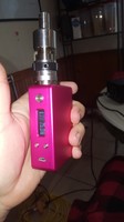
Alright, so I'm about 9 steps behind you guys, but my escribe has gone funky. My mod died on me a few months ago and I am just now getting around to building a new one. I finished my build (2s 18650). Before I installed batteries, I plugged her in to escribe to set it up for my battery config. I changed the battery config, then uploaded the settings..... Then I saw a new ver of escribe available, so I downloaded it. Now the mod tab has only kanthal power limit and manufacturer's settings. Nothing else. No battery monitor, no battery settings, ect, ect. I searched and found this thread, uninstalled escribe and reinstalled the recommended ver. Opened her up and low and behold, still missing everything in the mod tab. Help would be appreciated. Windows 8 if that's important -
I highly recommend just contacting evolv. I had 2 boards die on me back to back, which would normally put a bad taste in my mouth for doing business with a company again, but the customer support was so fast and helpful that I am considering buying another board, just to support the company's bottom line.
-
ah.....ok.....that makes sense. Come to think of it, I remember something about data connection and .5A from somewhere. Is that a common trait of many electronic devices? I'm obviously not very knowledgeable in this field, but I find it fascinating.
-
Hmmm.....do I have a bad battery or is there something going on with the board? Correct me if I'm wrong, but shouldn't it be drawing close to 1A with the cells so balanced and so close to being discharged? Also, is it common for the incoming amperage to be so......janky? It's also discharging at a ridiculous rate.....1/3 charge down to 10% in 5 moderate length puffs in TC mode.

-
Tonight, alas, I am too tired


