

Mad Scientist
-
Posts
247 -
Joined
-
Last visited
-
Days Won
1
Content Type
Profiles
Forums
Downloads
Posts posted by Mad Scientist
-
-
Yeah, test the tunnel diodes you think would be on the balance inputs. I think I see why you might be so frustrated. Uh boy . . . I should have seen this coming. Good luck with your venture. I'm sure you will succeed because after all there's one born every minute, right?SSV said:[.....I am assuming the balance inputs use a tunnel diode to prevent reverse biasing, so if the USB connection shorted and threw current against those diodes, that could explain some of this behavior....but speculation can run wild in these types of scenarios, so I would rather test, than assume....
-
Before you break out the expensive micro-probes and make your eyes dizzy under a microscope lol, did you use a pair of ordinary meter probes to actually measure what the balance connector is seeing? The pads the balance connector are soldered to are pretty big. Trouble shooting 101. Start at the beginning. Also, your setup sounds . . .unconventional. Can you post a pic of what you are actually using to obtain the results you posted?
both units were cleaned and inspected under the microscope for bad solder joints on the balance/charge circuitry....there are no visible faults. I am going to reflow the boards just to confirm that. The collection of SOT parts for the balance circuitry are directly under the B+ solder pad. That seems a bit iffy, if an end user applies too much heat to the B+ solder pad and doesn't use any kind of heatsink it's entirely possible to cause some issues there.....BUT one of these units worked fine for over a month, and then just randomly started exhibiting this behavior.
Both packs were verified charged and balanced on an external meter. Both dna200 boards were cleaned with appropriate cleaner, and inspected for bridges etc. On that note the conformal coating on the boards is not the best I have seen. Boards contaminated with e-liquid (inevitable in some designs) are showing signs of the conformal coating failing....
This has to be a monitoring error, either caused by software, or a component level failure (although microscope inspection shows nice clean fillets on all solder joints). 4.35 V is simply not gonna happen w/o some serious input failure....as you said the magic blue smoke would have been released if this was happening.
I don't really feel like getting the micro probes out and checking voltages across all those SOT pads, but I guess that is the next step. -
Nice job! That is a tight fit lol.
-
Lemo 2 has an intermediate connection between the airflow base and the build deck. I've had some problems with it also if that connection is not rock solid stable. You can try removing the airflow base, cleaning those connections, push the 510 pin in the airflow base in so when you screw it together the connection is tight, make sure the screw connection underneath the deck is tight.
I hate attys with intermediate connections or adjustable pins lol.
Lately I've been using billow v2 for tanks and velocity for RDAs. Just gravitated to those choices -- Rock solid, no issues. -
Something is obviously wrong with the cell measurements. Can you post a pic of whatever setup it is you're using to get those results? I'd also suggest that while it's doing that, measure each cell voltage across the balance connector pads on the board itself as well as the pack voltage at B+ B- with a decent DMM. For a freshly charged non-defective pack, if something were actually sagging one cell that much, the magic smoke would be released somewhere. You have to either have garbage in at the balance connector (why it would help to see what you have built along with actual measurements of what the board is getting on its side of the connector) or something wrong with the board. Last but not least, it is odd that it shows 0 Wh charge for an 11.94 V pack. My guess is it from the anomaly it sees on cell 3. As a possible red herring but I'll ask anyway, what are your pack settings in the mod tab? Anything unusual?SSV said:here is the same pack, freshly peaked on an external balance charger......and verified to be in balance with an external meter.....
dna/eScribe reads it as this though..... -
Thatguy said:
[QUOTE=Dejay]I think I've read somewhere that you can set escribe to passthrough (no balance charging) for that case.
awesome, thank you, I sure hope so. [/QUOTE]
If you're using actual batteries with no balance tap, your best bet is to bridge the taps with resistors to the batteries (if you use the "power supply" setting with actual batteries, it seems the mod won't handle low battery cutoff or have a settable battery meter).
Use 3 identical resistors, something along the lines of 1k to 2k. I'd recommend 1% resistors or better because they don't cost much for a few and it's more likely that the DNA 200 would then read the "virtual cells" as balanced or at least within 1%.
Using the notation for the balance tap of pins 1 to 4, pin 1 is ground: connect B+ to pin 4, run a resistor from pin 4 to pin 3, run another resistor from pin 3 to pin 2, run another resistor from pin 2 to pin 1, connect pin 1 to B-. Basically creating a voltage divider.
The DNA 200 will read the divided voltage across the resistors as "virtual cells" and operate normally.
MAKE SURE (emphasized) you set the USB charge current limit to 0. You don't want it to try to charge with no actual balance tap. -
According to the data sheet, stay at 0.2 Ohm or less for full 200 Watt capability and 0.4 Ohm or less for 100 Watt. I'm not positive but based on my own experiences, these are cold resistance values.
-
A common method seems to be to take a relatively thick copper wire and clamp it in the posts of a decent RDA. Mount that and measure the resistance reading. It will include the resistance of the mod, the 510 contact resistance and resistivity, and the same for the atty. I've seen it recommended to only use 80% of the measured value for safety. Apparently a calculated negative resistance would be bad.jschreiber said:Sorry for my ignorance on this one but how can I short the 510?
-
No worries but we must be on different wavelengths. It is supposed to power up on USB and potentially fire and read resistance and do all the stuff it does, but at obviously reduced power. This is not a fault or bug. The important failure mode is that blown fuse and I'm curious as to what caused that. If the board is doing what it's supposed to, that "can't" happen.vapealone said:
Well, like I have said, my hunting is over. I couldn't get any closer.
If Evolv will check/it flex it when they get it back, so be it.
But if it wasn't over, I would start from the other side
The only thing I can tell for sure that AA can work. So I would look at this function first checking how it can possibly be powered up, which circuit(s) must be closed etc. Than check all the possible bridging ways/spots that can close it w/o fuse)
Than check the circuits powered by USB close enough for some mechanical shorting if forced.... etc -
Might well be that there's something going on with flexing the specific board you have or possibly something more. I don't know how much time you want to spend hunting it down, but you could replace the fuse and then try to rerpoduce the issue. If the fuse blows when you flex the board, you've found the source of your fuse issue. Evolv would have to examine the board for comparison to determine if it's just that board or if there's anything more to it. Looking at the board, I don't really see how the USB connector could touch anything but maybe flexing your board had an effect.
-
It is rmaed. But I still want to know what happened and why to avoid it in the future if possible [/QUOTE]vapealone said:[QUOTE=VapingBad]lol, you don't need to do the math, just saying that seeing the analyse function working in your case doesn't necessarily mean the full operation is available, unless you have measured it happening. Like Spirometry said RMA it.
Well seems the good news is if it was a design issue with the board you'd see more folks reporting the issue on this forum. You seem to be the one and only.
Do you know what it may have been that caused the fuse to blow? Drawing > 25 Amps from the battery is supposed to be an unexpected fault condition. There have been several reports of blown fuses. I wonder if there are really that many careless builders (doubtful?) or if there's a trap for the unwary somewhere of doing x = blown fuse. -
I was watching Twisted420 do a DNA 200 mod review, and his description of preheat and the vape he was getting made it clear he never set things up properly. Here's the video: https://www.youtube.com/watch?v=xW_kZbT1ynk So I figure there's a need for a "quick start" guide so anyone can set the thing up just enough to get it going in a few minutes.
Here's what I came up with: https://www.e-cigarette-forum.com/forum/blogs/mad-scientist.136036/
Comments or suggestions welcome. -
vapealone said:
[QUOTE=VapingBad]The board powering for partial function via USB is not a bug, it is needed to program the boards without having to install them.
My concern is that the board powered via USB when the fuse is blown (i.e. board powered up w/o surge protection) With good fuse it is OK
Besides, as I have added, it does some other thing it probably shouldn't: the current actually found its way to the output circuit. And I think, it could be a problem. Unless there is some shut down hardware option inside, it means that few circuit on the board can get power from both the battery and the USB at the same time which sound like a kaboom to me
[/QUOTE] It would be interesting to see how much current it will try to draw from USB. Do you have any tools to measure that? (I'm not inclined to take a mod apart and disconnect batteries at the moment -- sorry lol). USB standard is (was? -- so many new versions out these days I can't keep track) that a device would negotiate with a digital port for amount of power available and a charging port (in addition to the specs for how to determine what it can supply) would lower its voltage if excessive current was drawn. As VapingBad stated, the board is designed to power itself from the USB with no battery present. The USB standard will (should) protect a digital or charging port from excessive current draw. This is true even if the mod tries to fire when USB powered. No kaboom. If you are still concerned about the issue, you should measure the current drawn through the USB when you try to fire the mod with no battery connected. -
Just tested here also. Working perfectly. Thanks again!
-
vapealone said:
[QUOTE=VapingBad]I see, the path would be through the battery monitoring/charging controller chip I saw someone post a link to the spec sheet for that a couple of months ago on ECF IIRC.
In that case it is hopefully controllable via firmware, isn't it? Or it is just wishful thinking?[/QUOTE]
I'm not sure that it's a normal operating condition to have the B+/B- to the battery disconnected but the balance plug connected and USB charging connected. Am I missing something? That's what I'm picking up from the thread.
Is that the concern? That when the B+/B- is disconnected but the balance plug and USB are connected it acts weird? -
My understanding is that if the board won't illuminate the screen and heats up on USB with no battery connection and you can't force a firmware update because escribe won't connect, it is toast.MuTong said:. . . . When connecting usb chip will heat. . . .
-
What happens if you disconnect the battery completely and then plug in the USB? The screen should light up. Also try to connect to escribe. Let us know the results.
-
Still need a temperature increment. And button function to be configurable. And . . . Lol. I'm sure it will all get done in time.
-
I'll have to dig out my old HTC phone. I'll bet John and James will enjoy trying to support, is it windows CE? Lol The serial interface through USB is pretty good. Im sure you'll see a 3d party app for android soon enough.
-
A pair of hemostats or even a large alligator clip do a pretty good job. In a pinch (no pun intended lol) large tweezers also do the job if you have a free hand to hold them.
-
Available now . . . Lol. http://www.cnet.com/news/forget-surface-microsofts-new-ipad-rival-is-the-windows-8-tablet/
-
Should be possible using the USB HID to at least get device monitor functionality over Bluetooth. I've got too many projects in the que right now to think it completely through but a simple serial interface through the HID would seem to be easy enough. You will likely have to write your own device monitor application. I will get to this; its on the list. I'm hoping evolv does it first though lol.
-
Could just be electrical noise in the environment. The 510 is an antenna, albeit not a great one, but with a noisy enough environment and given the low level signals the boards has to measure, leaving the 510 open might pick up enough noise to make the board think something is there. Do you have lots of fluorescent lights (or an operating Eimac tube lol) nearby?
-
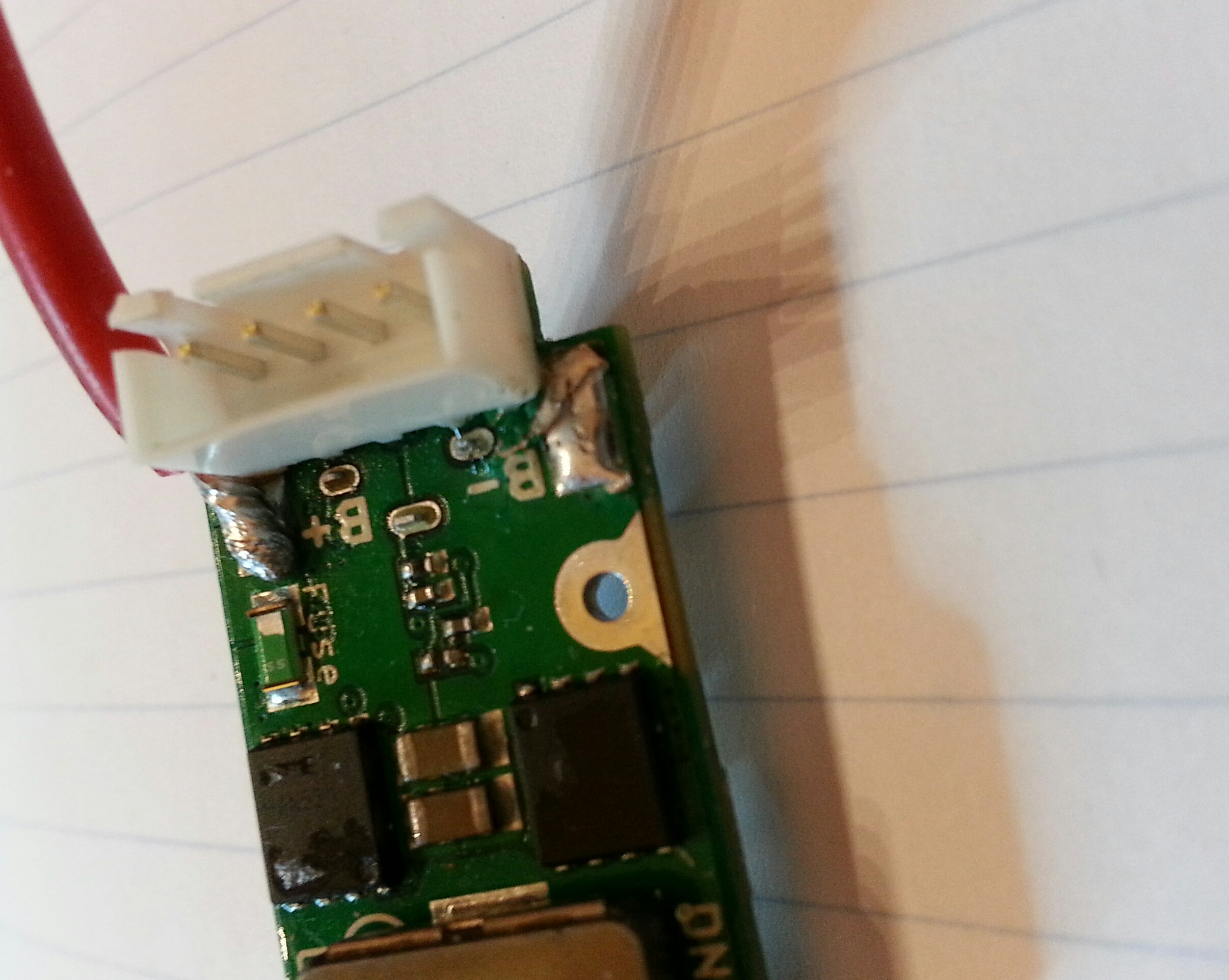
Balance connector ground is not connected to B- pad on the board. There are no obvious vias in the B- pad so you should be OK at least as far as the electrical connections. An assessment of whether this might affect power handling capacity of the trace is beyond my knowledge. Hopefully it's OK.bnitch said:I was trying to insert the board into a Florio box and ended up lifting the battery neg pad. it didn't seem to break the trace so I have superglued it back down. My main concern is could it have also torn a neg trace going to the balance plug.


Titanium TCR temps way off
in General Discussion
Posted