

Mad Scientist
-
Posts
247 -
Joined
-
Last visited
-
Days Won
1
Content Type
Profiles
Forums
Downloads
Posts posted by Mad Scientist
-
-
I guess there is a misunderstanding. What I suggested was to contact your mod vendor because your battery pack is likely no good. Nothing to do with any settings.
Wish I could give some other ideas but that seems to be the problem. -
I have found this specialized tool is also effective to remove pressed in 510 connectors.
 Place the frame over a hole in a block and give the 510 a few good whacks from the back side.
-
I would contact the vendor. Sounds like your battery pack might have issues. I vape all day at around 45 watts on a 17+ Wh pack with some capacity left over at the end of the day. 20 Watts on a 14+ Wh pack should last a lot longer than 4 hours.
-
That is a tight fit. Very well done.lexalove said:New member of the 69Modz family... I'm calling this one The "Stubby"
Hammond 1550P, FDV 510 and Keystone battery sled... all very heavily modified to cram it all in!
It's not the 'Final' design, it has some rough edges but as a beta I don't think it come out too bad. -
At some point, I guess I don't see why there couldn't be a power profile curve similar to TCR curve and battery discharge curve. X axis is time and y axis is wattage. Enter the values and it fires following the entered power curve. Unfortunately, I think that would sort of negate the whole concept of the board. Non-TC wire support seems more of a legacy compromise. For me, I can't taste anything from any variety of wire I've tried. I use a build that balances cold resistance in the range that works with surface area for the vape I want using wire material with a sufficient TCR at vape temps. For now Ti is best at that.
-
I think you guessed right. You definitely seem to have detached a resistor. Also, the ground wire on the balance pad looks to have a stray strand sticking out. Doesn't seem to be touching anything else but needs to be cleaned up so it never does. The photo isn't clear enough to tell for sure but you might be able to reflow the torn resistor back to the pads. OTOH, if a trace is damaged, the board is likely done.Flavored said:These microscopic things on the right?

Or these microscopic things on the left?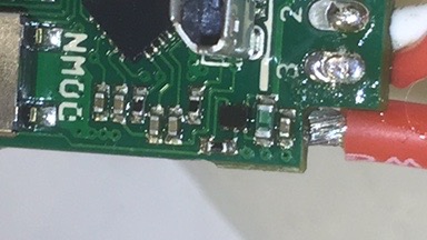
Or these microscopic things on the back of the USB (and above)?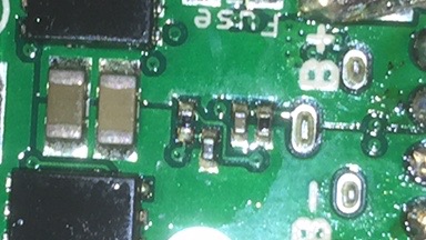
If I had to guess, that one on top of the first pic doesn't appear to be properly attached. -
Hi Mike, Looks like you need a few more lol.Mike Vapes said:
-
Must just be you lol. Been using dual 18650 with no issues. Evolv made it public enough on this forum that I could build it. I guess I don't understand exactly what data you're looking for. I've experienced no instability and only feature lost is a full 200 watts for the 133.601broken said:Ya know is it just me or doesn't it seem as if even with everything setup/wired properly that the DNA 200 when in 2cell / dual 18650 has stability issues? It seems the chip looses its reverse battery protection, also it seems to also loose it's cell monitoring feature aswell & quite possibly it's low cell cutoff point. Is there any reason Evolve doesn't have a public 'schematic' for dual 18650, yet there have been firmware updates to support the feature, but no schematic. I love evole's products, but with this chip I don't understand the lack of information , even with it being a newish board. Have I missed something that EVOLVE has made public of the dual 18650 setup & acknowledging the feature losses / instability? Any information would be appreciated.
-
As another idea, increase the surface area of the head of the screws. Solder or silver solder the screws to thin pieces of steel as a "sled" then use the preferred adhesive on the steel to mount in the box.
-
Brady said:
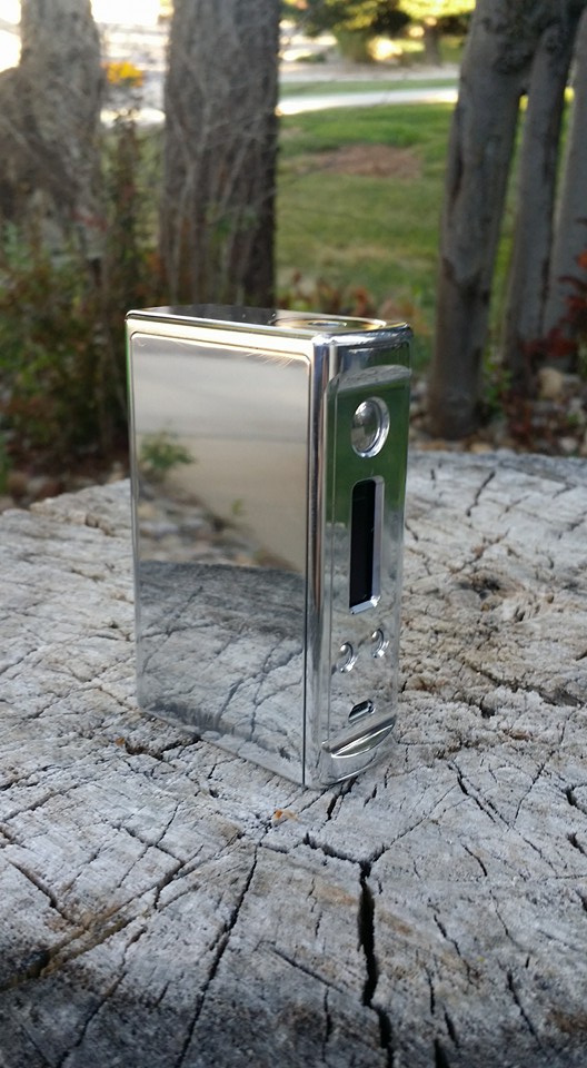
Received our first prototypes of the Evo. This one has a polished finish without engravings, where the production versions will be anodized.
Is that going to be commercially available? Looks great. -
Here's an example of a "runaway" coil: Test setup: plume veil with .005" type-E thermocouple fitted to central wrap of 3 wraps 26 AWG Ti; Ocean Controls thermocouple board with added PIC12F675 programmed to interface to PC (the 8 pin PIC is in a 14 pin dip socket because I might go with a 16 series PIC down the road). The PIC reads the temp and sends ASCII csv values to the PC. These are then saved to .csv file and charted with Excel. Data points are 100ms apart (10 per second). Data is presented as degrees C. The first tiny little increase hump was, I believe, the DNA 200 reading resistance. Then the first two smallish "humps" in the chart are quick clicks to lock, set desired temp, then quick clicks to unlock. DNA 200 is fantastically fast to fire as these were very quick clicks. It started heating a little at each set of 3 quick clicks. Best performance of any mod I've used. DNA 200 set to 100W preheat for 1 sec punch 7, then 75 W max. The huge spike is the first fire on the coil, almost 470 degrees C peak (!). The second nice plateaued line is the second fire, normal temp regulation. The DNA 200 obviously didn't like something about the coil on the first fire. It immediately "settled down" for the second fire.
-
John, James, Brandon:
Can you steer me to a convenient (hopefully) pad on the board where I can pick up +3.3 or +5V? I need to source about 100 uA continuously and 800 uA peak at anywhere between 3.3 and 5V. I'm assuming that just tapping a battery across the balance connector might screw up the low bat and balance charging.
Thank you! -
I had also asked about this. In the mean time, I plan to add a third button the the mod that is "both" -- function is to make the DNA 200 think both buttons are pressed (the buttons both use ground as common so any momentary contact N.O. double pole switch in parallel across the up/down button pads on the board or a single pole switch connected through steering diodes will work fine). It also helps to change the lock sequence to 3 clicks instead of 5.
I likewise seem to change temp often enough and I want to be able to do it more easily (like while driving).
While we're at it lol, 10 degrees F per click is too much. I'd like to be able to set the increment as a parameter also.
And as long as I'm daydreaming on the topic lol, having to hold "both" for 2 seconds is too much. If I press both that means I want the function of pressing both -- do I also have to let it know I really mean it by holding for 2 seconds lol. -
The N80 wrap will actually slightly lower the already low TCR of SS for the build as a whole. Can you wrap with SS?
-
Droopydroors said:
That is not true... The problem is with the chip and its features!!!! That is exactly what the problem is. Listen if I want to vape in temp mode and have my settings set to TEMP MODE then it should stay there regardless if I have the correct tcr uploaded. It would just be running at the wrong temperature. So don't push the blame on to the wire I'm using or the wire companies not releasing info. This device has the ability to run some crazy builds the way you want them to run but its getting kicked out due to a chip "safety" feature. Makes zero sense and a firmware update could fix the problem.
OK, let's solve the problem step by step. Keep in mind that the board wants to see a minimum level of temp increase as it applies power and the only way it has to detect a temp increase is to calculate it based on resistance increase of the wire applied to the TCR curve so . . . if the TCR doesn't match the wire configuration you're actually using, it won't and can't work properly. It is definitely not the same as prior more primitive TC mod technology that just calculated a target resistance from the TCR and temp setting and didn't care what that is.
So exactly what wire are you using in what build configuration? What TCR curve are you using?
I'm sure someone here can figure out a workable solution. There are guys here using SS coils successfully and I myself go with Ti / Kanthal claptons without issue, so as long as the build has at least some reasonable resistance sensitivity to temp and is stable, there is a TCR curve that will make it work well. -
Since a 100 ohm resistor was specified if I remember right, I'm guessing closer to 3.3V. That would allow about 15mA forward current through the led, also factoring in the led voltage drop.Raito said:yeah yeah above the F I saw them, I connect the resistor to the one toward the middle and to the "+" led and the other to the "-" and the other two like normal..... voila? right?
it's 9 volts right? -
Valgore said:
I think it's a great bit of kit, It's the V2 so all the issues it did have are now gone. The only issue I do have is not knowing about the battery.
You can let 'er go through 5 or 10 charge/discharge cycles over the next few days to work in the pack and then run battery analyzer and case analyzer. In the mean time, 11.1V x 1.3Ah = 14.43 Wh. You can use 14.43Wh as close enough. The battery is very likely around 1,300mAh real capacity. As far as I know, the only thing the battery setting affects is the battery gauge (although I wonder if it also affects charging).
If you still like it after a few days, please let us (and me) know. I suspect everyone not having problems are remaining silent so the only things I've read are problems. -
While the battery capacity is getting sorted out, what's the verdict on this thing?
I'm thinking about maybe getting one -- the over the top red case is interesting -- but haven't seemed to have heard much from anyone not having some sort of issue with the thing. Is the squeeky wheel getting the grease or is it really a dud?
Thanks for insight from anyone who has one. -
Raito said:
I know it's a clumsy question, but I used to connect these to unregulated box mods, and DNA chips is kinda new to me.
"If you look below the fire button you will see 4 small solder pads. Attach a 100 ohm resistor between the 2 pads on the left above the screen-printed 'F'. Resistor link
Above the fire button, near the board edge and slightly off to the right, you will see 2 identical small solder pads. Attach your LED there, cathode side toward the middle of the board.
That will give you what you want." the small solder pads are these two small circular parts ? just need a diagram because I can't imagine it, and what to do after that?!
The small pads are below the fire button. The word "FIRE" is silk screened on the board. The pads for the resistor are to the left, above the "F" in "FIRE" just as the instructions indicate with the pads for the led to the right, just as the instructions indicate.
It's hard to describe but if you look carefully at the board right where the word "FIRE" is silk screened, you will see them. -
Droopydroors said:
This is the most annoying thing about this device!!!!! So you have all this customizable software to set up profiles. You have a profile set to TEMP CONTROL but the device decides "nope this isn't temp control" drops out and you get blasted with 115 watts of burning hot vapor. Why have the software if it does nothing! If it drops out of temp ,make it throw an error code , instead of running in wattage mode. This is so damn annoying!!! So let me explain. Ive been running temp control since its birth and I have certain RDA's I use for it do to there amazing connections. Right now I'm running a parallel Ss alien fused Clapton. I have a custom tcr uploaded. When it works its amazing and vapes like no other. All the advantages of an amazing flavor and wicking coil without the millisecond hit you would usually have to take in wattage mode because you can keep the temperature to your liking. But then out of no where BAM it decides to drop and you either get scalded by your device or your re wicking because the cotton is burnt!!!!! This device has great potential to get us out of those coils that we used back in 2002 in a ce4. Because we have came full circle and we are there again wrapping spaced coils with 30 gauge wire!!! Please, please, please put a temp lock on either the software or the device itself!!!!
Thank you and sorry for ranting
FWIW, I tend to agree with you. My guess is it is set up the way it is because kanthal users who don't go deep into escribe would have trouble with the device if it didn't automatically sense a coil that doesn't increase resistance much with temp.
As a work around for now, set your wattage only about 5 or 10 watts above what the coil can handle non-TC. Then if it jumps out of TC, the max wattage will be limited to an extra hot vape instead of burnt cotton taste.
If you want a really exciting vape, see what happens in TC preheat if a wrap shorts and resistance drops during the preheat. Yup, all 200 watts is on tap to get that resistance back up -- blech lol. At the end of the day, it's a sophisticated device and the build does have to be stable for it to work the way it's intended.
As a coincidence, not 30 minutes ago I turned a 28 AWG Ti, 34 AWG A1 clapton into 3 sections separated by small gaps of vaporized metal after straightening out a coil I thought was drooping more than I liked. I'll never know exactly what went wrong but obviously the resistance changed as it heated in some unanticipated way and bye-bye coil.
In any event, it would be nice to have the option of telling it not to ever automatically switch to non-TC mode. Stop delivering power and flash a message: "Hey, Mad Scientist, your build sucks" or anything lol. -
vidalcris said:
Thanks for your help
")
I will send back the board to evolv today ! i hope that will not take too long to come back to me.
I was thinking about the ground problem today..
If i well understood, we can use the ground or not, this is not a problem. But if we use the ground we need a good connection right ? maybe the problem was that .. because the box is aluminum and there is only two screws to maintain the dna200 :-/
I think it is always better to use a wire to connect the 510 shell to the board. Using the mod box itself as a conductor requires a bit more than most DIY builders (and apparently some big mod manufacturers alike) can reliably do. There is a reason why homes with aluminum wiring burned down. Aluminum oxidizes and aluminum oxide is a great insulator.
So the takeaway is, use wire to ground the 510. It's only one additional wire and one less issue to have to deal with. -
The entry under history looks peculiar. Those are not English characters.
-
Hello @Rocky2015, any updates? I've been stalking vaporDNA, VapeNW, VaporBeast, wetvapes, vape95, etc., etc., hoping to see "in stock" appear. No joy lol. Thanks for any info.rocky2015 said:[ @Mad Scientist Thank you! The DNA200 is a great board, it absolutely gives us a lot of motivation to design and build, and we are eager to build a solid and reliable mod with it, at the same time maintain the asthestic apeal which we always strive for. The Esquare dna40 was a great success, and we have constantly been asked by customers to build with the dna200 based on the same formfactor and design concept since the day we released the Esquare, now it's about coming to real life. We have been testing prototypes and revising design details lately, final production will kick off in a week's time. The estimated shipping date for first batch is around 10th September. Most of our Esquare retailers will carry those as well. You may also follow our FB page for updates and retailer list. Stay tuned! https://www.facebook.com/LostVapeLtd Thank you! Rocky
-
Your English is good enough! I understand what you mean.
In the General tab, pick a profile and choose Custom for coil material. Toward the right side of the screen under the graph, click Special and enter the wire TCR directly.
On the mod, select that profile (power setting locked and double click either up or down then click to the profile number you set) and vape away.
If the setting was 105 for the stainless you are using, I think that translates to 0.00105 TCR


Short battery life vt200
in Batteries and Charging
Posted
You are right of course. But I vape pretty much all day, about 20+ml per day at 100 watts preheat, 75 watts setting and around 45 watts at the "ebb" of each draw -- so that's my point of reference and comparison. At 20 watts to get only 4 hrs use from 14+ Wh, that would be some pretty heavy duty vaping.
But again you are right -- the guy might just chain vape like a boss then wonder why the battery gets drained lol.