

Mad Scientist
-
Posts
247 -
Joined
-
Last visited
-
Days Won
1
Content Type
Profiles
Forums
Downloads
Posts posted by Mad Scientist
-
-
For diagnosis, consider measuring the voltage actually on the balance connector pads versus what device manager reports. If they differ, it's the board; if they don't, it's the battery or wiring.dwcraig1 said:So here is a screen shot of why I'm replacing the battery although I'm not exactly certain that the battery is the problem. I disassembled it this morning and found some kind of crude built up on #3 solder joint of the balance connector. I probably should have re-soldered it after I cleaned it off but it looked good. I'll find out when I replace the battery I guess. I tried charging it with the rc balance charger that came with my Hotcig DX200 and all it did was overcharge the two good cell to 4.28 volts. Since failure charging with little RC charger I'm pretty sure now that the battery is at fault here.
![[image]](https://scontent.fsan1-1.fna.fbcdn.net/hphotos-xaf1/v/t1.0-9/12189937_1093782013979355_823007213321644645_n.jpg?oh=0f5cabe12215d3c25a6bdcf544d9ba06&oe=56B55E08)
-
It will send current through the 510 as part of the resistance refinement process. Possibly maybe this is what you're seeing.Andymilneruk said:I should have said it has been working fine since the fuse replacement, I just will not be using it until I get to the bottom of the sparking situation. It seems to be constantly putting a voltage to the 510 even when the board is sleeping.
-
That is odd behavior. I actually want mine to do just that lol. The second set makes sense (note that according to evolv, the TFR is also a dependent variable when describing behavior of ohms lock range when it assumes a new atty). 0.09 to 0.06 is a drop of 33% so it should ask. 0.06 to 0.12 is an increase of 100% so it should ask. The first set I don't get. 0.06 to 0.12 is an increase of 100% it should ask, so that's ok. 0.09 to 0.10 is an increase of about 11% so it should not ask. Odd. I set it to 5% and it prompts. But that's exactly what I want it to do.VapingBad said:I just tried a few with range set to 35.16% 0.06 to 0.12 go prompt, 0.09 to 0.10 still got prompt
With range set to 20% 0.09 to 0.06 got prompt, 0.06 to 0.12 got prompt -
As another point of view . . . (which I copy from the other thread -- not my original thoughts lol) If the new atty is within the ohm lock range of the previous atty it won't ask and it assumes it's the same atty. If the new atty would have to be colder than -100 or hotter than 800 degrees F given the old atty cold resistance and the TFR curve in use, it won't ask and it assumes it's a different atty. Else it will ask. If you want it to ask for different attys that are close in resistance, reduce the ohm lock range.
-
I think this thread may help. I had a similar question about what the ohm lock range exactly does. https://forum.evolvapor.com/topic/67982-topic/?do=findComment&comment=911752 Reduce your ohm lock range to a low enough percentage so it asks when you change attys. How far apart are your attys in resistance? Mine tend to run less than 10% difference for an "identical" build. I don't care if it asks every time I remove and replace an atty as long as it asks every time I change attys, so a low percentage range works well for me.
-
I set and leave my wattage at 75.x watts (with x being wattage set in the profile in use so I can see at a glance which profile is active). I adjust temp to anywhere between 430 and 490 to taste. 450 is usually just about right but I still adjust it up and down at times depending on what I feel like at the moment. Using device manager to see what it's doing, my attys tend to tail off at the end of a draw at anywhere between 25 and 50 watts.Milkweed said:Noted. With that said, what temperature and wattage are you firing at? I had mine at 0.0038, set at 450F and firing at 35W. Am i doing it right? Seems better then what it was with my first experience.
-
When experimenting with wire TCR I don't bother to work up a polynomial curve. Just enter a TCR value in the "special" entry box (Ohm coefficient per degree Kelvin). My recollection is with unkamen Ti I use 0.0041 and with a 26 AWG Ti wrapped with 32 AWG kanthal I use 0.0037.Milkweed said:Anyone else was successful with such build and uploading the csv file into escribe? @Mad Scentist perhaps you can share your csv file here....
-
Were you able to resolve the issue?Jvape78 said:I do have 1 issue left to resolve. I keep getting a weak battery alert on screen when my battery bar is 3/4 full still. . I plugged it into escribe and the picture here is the readout. Everything looks right. Cells 1&2 reading 3.8 and cell 3 is reading 1.25. I know they set the limit to 1.5v on cell 3 so I'm under that. . Only thing I can think of is maybe the tap connection at the battery tray is not perfect and if it jumps up over 1.5 it causes the chip to enter 3s mode and then thinks the battery is low on that 3rd cell. But it never gives the message when the batteries are fully fresh and you'd think a connection issues could cause the message to be seen at any time..any other thoughts before I warm up the soldering iron?
-
I think realistically, many if not most people sooner or later either most of the time or at least at times try to wring maximum possible performance from an atomizer/build. Once you get accustomed to "more" the tendency is to want "MORE." This trend is readily observable in each next turn of atty design (like every two weeks it seems lol ) and in the demand for boards that can deliver as many as . . . 200 watts.James said:. . . and have come to use the temperature protection to achieve 'absolutely the maximum possible amount of vapor for this atomizer, while keeping at a safe level'. That's fair, but it would be better if the atomizer design was such that you never needed to hit such high temperatures to get good amounts of vapor.
") One attraction of temp control is to be able to get best possible performance (admittedly assumed to mean ever larger amounts of high density vapor) while avoiding excessive temps (excessive meaning either adversely affecting strength/quality of flavor or producing a harsh flavor which usually includes nasty juice decomposition byproducts). Another plus is the ability to set a temp that delivers the flavor performance desired, which is almost always a lower temp than max vapor output.
As the temp setting necessarily affects power, I can get the vape I want by adjusting either. My choice is to adjust temp and allow the device to do what it's supposed to by limiting temp through its modulation of power. To me (and many others) I don't need to be warned that it's doing what it's supposed to do.
One attraction of temp control is to be able to get best possible performance (admittedly assumed to mean ever larger amounts of high density vapor) while avoiding excessive temps (excessive meaning either adversely affecting strength/quality of flavor or producing a harsh flavor which usually includes nasty juice decomposition byproducts). Another plus is the ability to set a temp that delivers the flavor performance desired, which is almost always a lower temp than max vapor output.
As the temp setting necessarily affects power, I can get the vape I want by adjusting either. My choice is to adjust temp and allow the device to do what it's supposed to by limiting temp through its modulation of power. To me (and many others) I don't need to be warned that it's doing what it's supposed to do. ") Luckily, you guys allow that to be configured so we can turn the warning off.
Now if we could just get the up/down to adjust temp instead of power as another configurable setting . . . and allow configuration of the temp bump per press . . . (should I duck lol).
Luckily, you guys allow that to be configured so we can turn the warning off.
Now if we could just get the up/down to adjust temp instead of power as another configurable setting . . . and allow configuration of the temp bump per press . . . (should I duck lol).
-
There have been.VapingBad said:I am amazed there have been no requests for temperature increment I often have to use Escribe, both my 200 are set to 382 F ATM.
Along with requests to make the unlocked state adjust temp rather than wattage (table driven state machine for the ui so we can set all "that stuff"). It will get there
-
Good idea. I will definitely do that. Thanks again.blueridgedog said:A small O ring under the post will allow more torque and better internal contact while still letting the tip stick out just enough for the 510. I have 8 GTs and three of them are crap for TC vaping for that same reason. A .25 build slips to .35.
-
Strip the wire about a half inch or more. Twist the strands together so they are smooth and tight together and then tin the wire. Snip off the excess length after tinning. Then insert the wire in the pins's solder cup and solder. I've gotten 12 AWG in there so 14 should fit. I know you already have the FDV but the Varitube 510s are definite better and cost about the same.xtremeo07 said:I have been trying to figure out how to get the 14 gauge positive wire to solder into a fatdaddyvapes V3 510 pin. It doesn't fit perfectly and some strands always poke out of the solder join. Any suggestions?
-
Thanks to you both. Makes sense. So I'm going to set it very narrow and that should pretty much do it. I still hate adjustable 510 pins on attys lol. I've been tightening them as tight as they will go which seems to help a lot. The only "gotcha" there is when resistance increase a lot due to an intermittently bad connection between the pin and the post and it thinks it has to be a new coil when I replace the atty. The resulting vape is, shall we say, warm lol.
-
blueridgedog said:
[QUOTE=Mad Scientist] What I'm trying to accomplish is having it ask every time I change attys, whether very close or very far off.
Have you tried 1% in the range then so that the assumption for same coil is the smallest? There appears no way in escribe to set the other end and reduce the frequency of it assuming it is a new coil without asking.[/QUOTE] Hi Blueridgedog, haven't tried a whole lot of experimenting yet (seems silly I know but I have so many other small experiments here and there going on -- I figure somebody knows what the setting actually does lol). So the way it works is if I reduce the ohms lock range to a small percentage, it will ask if the reading delta is > the specified percentage of the old reading? I wish all the process parameters could be set in escribe. The whole "automatic transmission" analogy is great except in the real world where I have attys with adjustable pins that often suck at just maintaining a stable static resistance -- I want the mod to ask so I know I'm about to get a nuclear blast of a vape if I don't do something about it. Also have a bunch of attys with identical builds very close, but not identical, in resistance -- it seems to assume they are actually identical. I presently have it set to 10% and before I really dig in to futzing with it I was hoping to know what it really does. Anyway, you seem to know the function of the ohms lock range setting -- what exactly does it do? Thanks. -
I'm sure it's in the manual somewhere so I apologize if I'm being lazy but can someone definitively explain exactly how the ohm lock range parameter functions? I've read at least two different explanations: Say you remove and replace an atomizer: 1. If the new reading is within ohm lock range of the previous reading, it won't ask new coil and assumes it's the same atomizer, else if outside the ohm lock range it asks. (But if this is the case then there's another wider delta where it assumes it's different and doesn't ask, just assumes it's a different atty). 2. If the new reading is within the ohm lock range of previous reading but outside some other fixed delta, it asks, if it's outside the ohm lock range, it assumes it's a different atty and doesn't bother to ask. The problem is there are two states where it doesn't ask -- so close it assumes it's the same atty and so far off it assumes it's a different atty. What I'm trying to accomplish is having it ask every time I change attys, whether very close or very far off.
-
Based on how the software and hardware work, it will do these wires just fine with TC on or off. If you set preheat to zero seconds and TC off, it will behave to the user as if it were just a VW mod. It tracks the resistance in real time and varies voltage to deliver the desired wattage.valld said:I don't think DNA 200 is designed to handle properly Ti, Ni and SS wires in Power mode (Temp control turned off). It will be best if Evolve crew chip in here and explain what happens if you try to do this, and if it's at all possible or not.
-
Ordered a silver one from wetvapes. Should have it in a few days.
-
Wow, I'm not even sure I'm seeing what I'm seeing. Is that some type of paper thin wood veneer done like a sort of wrap? Looks very cool!dwcraig1 said:Coming real soon, Hotcig
![[hot1]](http://s9.postimg.org/5ml04e1jj/hot1.jpg)
-
If you use a wire from the proper pad on the board to the 510 shell, you don't need to worry about a good connection from the board to the case.JTree said:Well i'll do some through bolts, then.....but it's after I ground to the case that I connect the battery?
-
Milkweed said:
[QUOTE=Mad Scientist]I've used dual claptons wrapped as you describe. I found that the TCR is lower than just plain Ti. You may need to adjust your TCR down by about 0.0005. I would not make any adjustments to actual cold resistance (it is what it is). If you're sure its running too hot on a stable build, reducing the TCR will reduce the temp. Steam engine is pretty good but not always perfect, and the exact wire you have may differ from what steam engine thinks both in resistance per length and TCR. Also keep in mind that a good set of claptons will tend to produce a hotter vape.
Let me get this right. So if my TCR was 0.006 I have to bring it down to 0.001 or just 0.005? And I think you mean 0.005 as the range is only 0.001-0.01. I also noticed in the temperature control results equivalents tab, it mentioned "To match it on a mod set to Titanium 1, adjust the temperature to ~210°C or ~410°F." and so I did. Seems a lot better than before. It was at 450F previously. What is this Equivalents tab suppose to be for? Oh....and thanks for the help.[/QUOTE] If your TCR is set to 0.006 and you think it's too hot, bring it down by 0.0005 to 0.0055 and see if that's cool enough. For Ti grade 1, 0.006 is on the high side. I use 0.0041 for Ti wire I got from unkamen and I've actually measured the resulting temperature to be very close to spot on. The equivalents tab on steam engine is for setting up mods that can't change TCR and are permanently set for Ni200. DNA 200 doesn't need that.
-
I've used dual claptons wrapped as you describe. I found that the TCR is lower than just plain Ti. You may need to adjust your TCR down by about 0.0005. I would not make any adjustments to actual cold resistance (it is what it is). If you're sure its running too hot on a stable build, reducing the TCR will reduce the temp. Steam engine is pretty good but not always perfect, and the exact wire you have may differ from what steam engine thinks both in resistance per length and TCR. Also keep in mind that a good set of claptons will tend to produce a hotter vape.
-
Yes, would work. If you give 5V to the USB on Vbus and ground to the DNA, it will be happy to charge. The connector design could use magnets or just the weight of the mod and gravity to make a good connection. You would need to include either an electrical or mechanical method of preventing backfeeding a computer supply if accidentally connected to USB while on the charger stand. The design of the stand itself could easily incorporate a shape that would preclude mating the contacts while a USB cable was connected. Here's the pinout diagrams (jump to the pinouts section). https://en.m.wikipedia.org/wiki/USB#Mini_and_micro_connectorsNickIcon said:I'm in the process of designing a custom DNA 200 box mod and am thinking of making a charging stand for it as well.
Originally I had been thinking of using an inductive charging module a-la VaporShark rDNA40. Given that I would be making something on the bottom to align the mod on the stand anyway it seemed like a better idea to turn those into the contacts rather than bundling in the extra wireless charging components.
Here's the concept so far: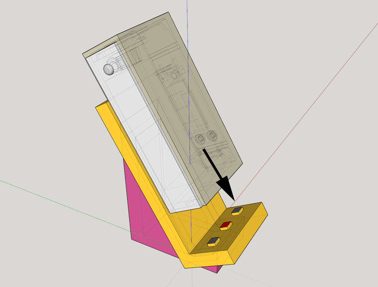
The mod has matching female contacts on the bottom: two grounds on the outside and live in the centre so that the mod can be put down on the stand either way around.
The priority is to make the connection easy to make so I've dropped the idea of moving the mod-side USB port to the bottom: I don't want the mod to "stick" to the stand when it is removed and I want to avoid having to align the USB connectors (and then push down) when it is placed on the stand.
Of course this means that the stand will serve to charge only and that the USB port will still be required to connect to a computer to use Escribe but where day to day use is concerned I'm more than willing to make that sacrifice. On that note however, I'm sure that the on board USB connector could be removed and all contacts re-routed to a custom connector with all 4 USB contacts but I'm reluctant to make any changes to the board itself.
My intuition says this shouldn't be too difficult - find the positive and ground that the USB connector connects to on the board and solder on the leads to a connector on the mod that fits to the stand.
On the other hand my understanding of electronics is limited... Other than not having the mod connected via the USB port and the to the charging stand at the same time, can anyone enlighten me as to whether this would work or not?
The follow-up question is where to solder on my leads to the mod's stand connector - without compromising the existing USB port.
Any help would be much appreciated! -
Once the magic smoke is released, it's a goner. Maybe open a ticket with evolv so they can try to determine how it may have failed.
-
Avionic quality wire tinning method (in case you want to fly it lol). Antiwicking tweezer http://youtu.be/_ZivEBZzsYs Procedure http://youtu.be/xpiyB7ZM3vg

Want to get another DNA200-suggestions?
in General Discussion
Posted
Out of the "readily commercially available," another vote for the lost vape efusion. I've only had mine a couple of days but it seems well made and none of the drama I've been reading about with some of the other mods out there. I can't get over how light it is either. Feels like there's no battery in there it's so light.