

Ak89
-
Posts
37 -
Joined
-
Last visited
-
Days Won
1
Content Type
Profiles
Forums
Downloads
Everything posted by Ak89
-
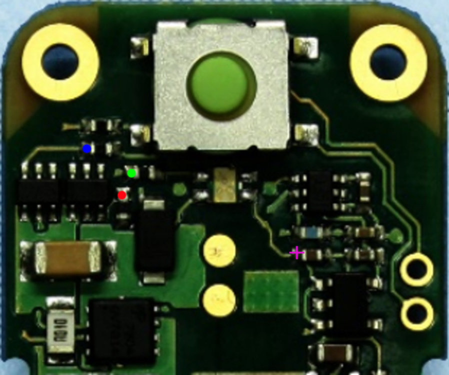
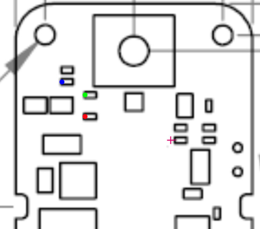
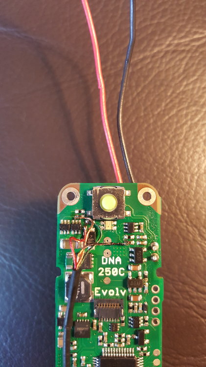
Hopefully this is kind of what you were looking for. Images pulled from datasheet, marked with colored points to denote solder locations. I'm glad to help. Feel free to ask questions. I will provide any info I can.
- 15 replies
-
- 1
-

-
- 250c
- led switch
- (and 1 more)
-
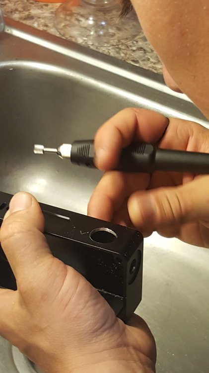
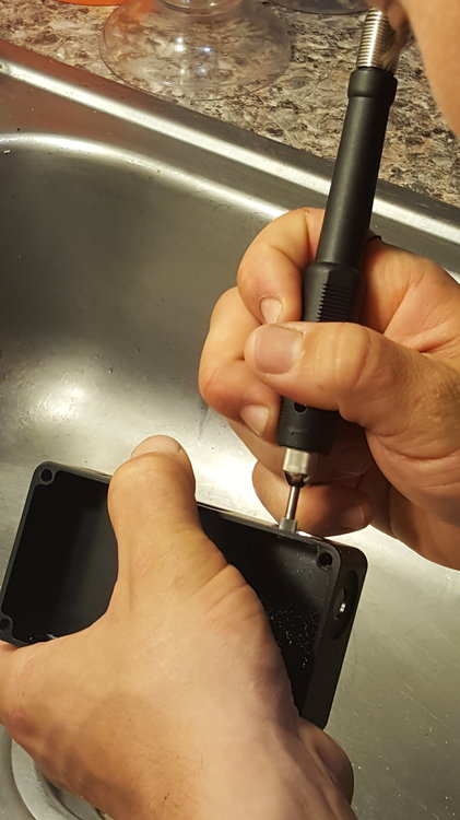
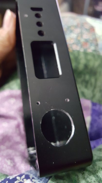
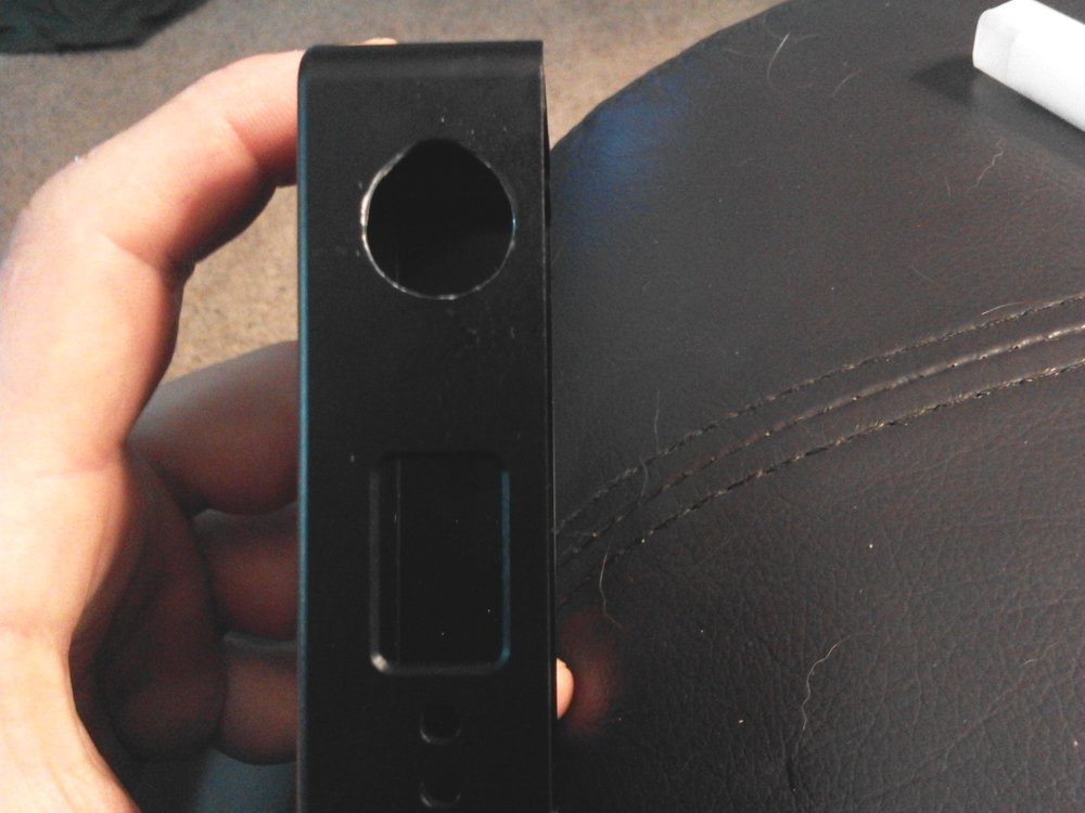
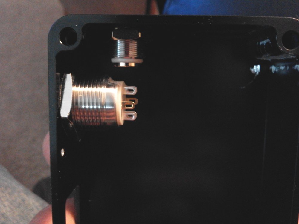
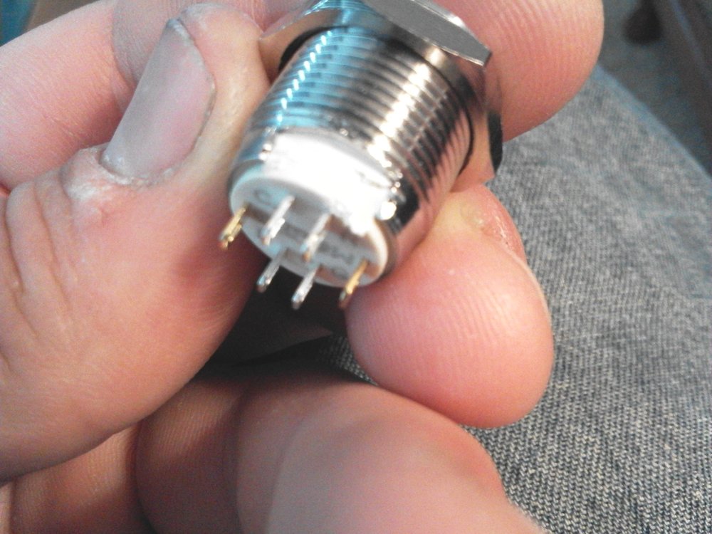
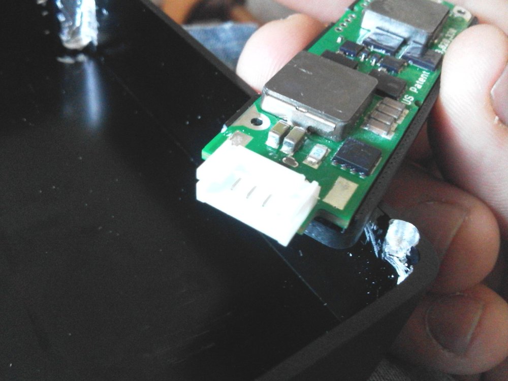
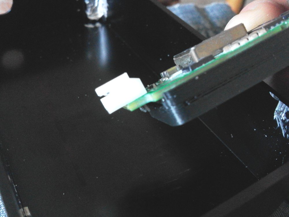
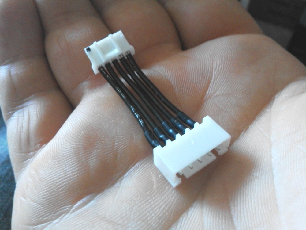
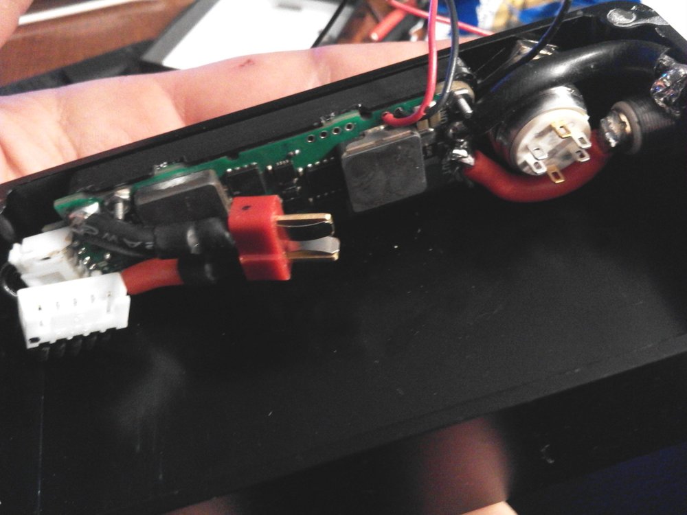
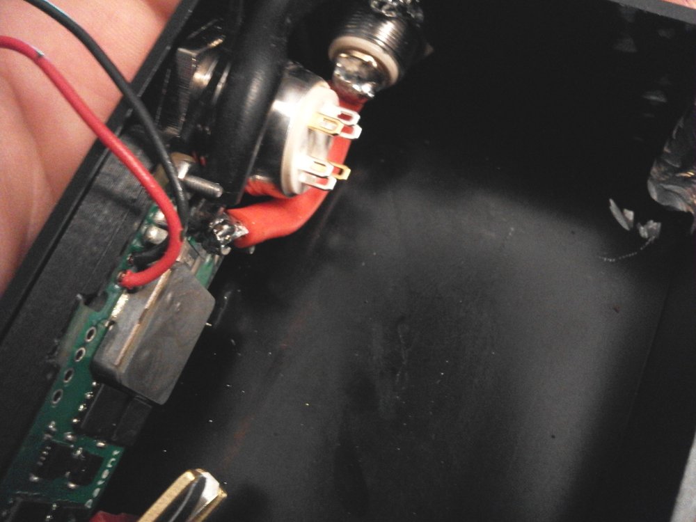
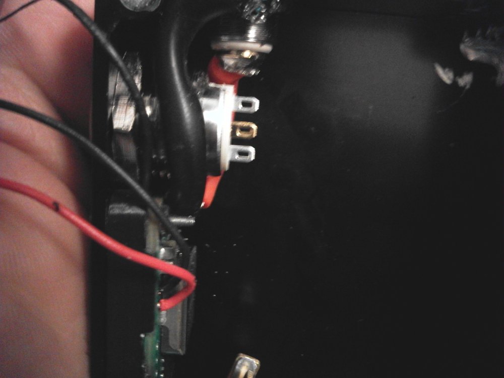
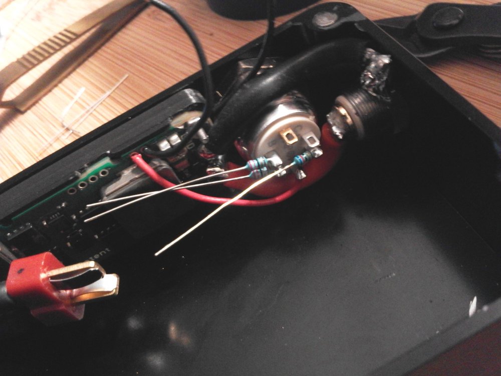
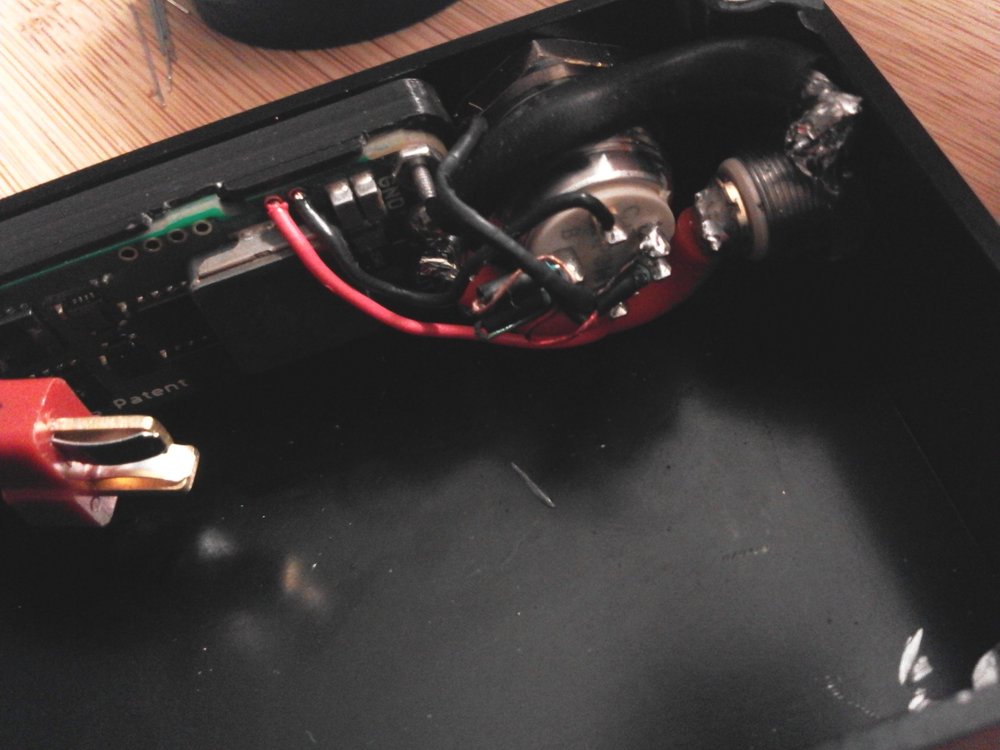
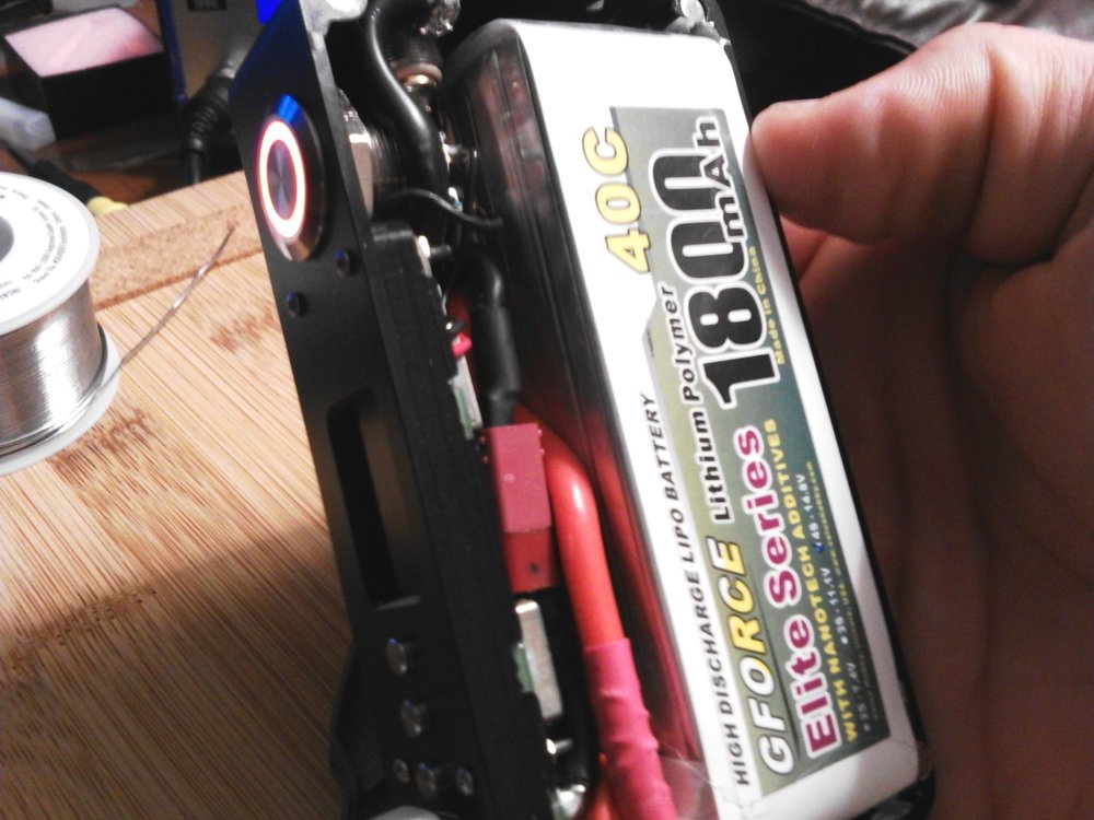
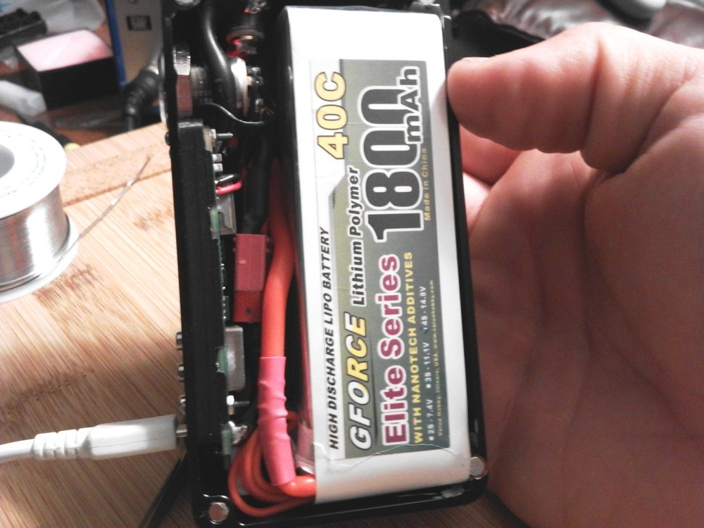
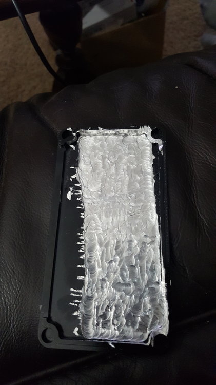
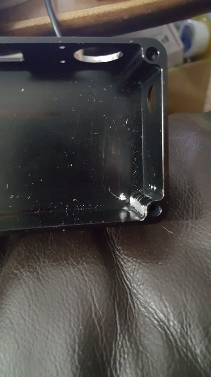
ATI B box ONPOW 16mm RGB momentary pushbutton (Common Anode, WITHOUT Resistor) GFORCE 1800 mAh 4s "Elite Series" 40C LiPo Varitube V2 510 Connection 12 AWG Silicone Wire (Battery and Output) "Deans" T-Connectors JST-PH Right Angle Balance Connector Custom JST-PH to JST-XH Adapter ...And LOTS OF DIE GRINDING!!!! I ground a 16mm cutout downward from the original 12mm CNC'd hole. Moving it as far as possible from the 510 without leaving a gap that wouldn't be covered by the switch bezel. However, there was still a clearance and shorting issue. So.... More grinding on the switch. I wanted the largest possible battery I could fit in the box, but that left concerns with the balance connector. I went with a right angle "PH" header on the board, and adapted that to the "XH" that comes standard on most batteries. I was already going big on this build and decided to push the limits running 12AWG wire throughout. (I know, beyond datasheet spec.... but I made it work.) Aluminum sinks heat very well, hence the ugly 510 ground. Just couldn't get things hot enough. I attached directly to the brass nut. Wiring the switch was tricky. ******************I don't recommend anyone try this unless you are VERY confident in your skills at soldering tiny points.****************** Black (ish) wire to the right is common positive (+) voltage (3.6v regulated). Gold/Copper wire is "blue" LED ground point. Red and Green wires are the ground points for their respective color. ***NOTE: Solder points are chosen to avoid using the onboard resistors. (ie. Attached to the side opposite the LED) I run my own "external" resistors at the switch... Resistor Values that I used: (A bit higher might be desired, since these values put the LED current beyond spec and a bit too bright, and probably affecting overall lifespan of the diode(s).) 62 ohm - RED 22 ohm - GREEN and BLUE And the battery ended up being larger than stated on the website by a mm or two in all directions, which required even more grinding to allow for clearance. Primarily on the lid. Not pretty, but necessary. But everything fit. Not much space remaining.... In case someone asks: Yes, I partially unwrapped the battery to slide the reinforcing shrink tube down the wire. I needed the additional bend radius.... I apologize for the quality of some pics. Build happened over numerous days, different lighting conditions, and a couple phones/cameras.
- 15 replies
-
- 2
-

-
- 250c
- led switch
- (and 1 more)
-
Have not tried a psu, but there is an escribe setting for it. I believe it is in the battery tab. Not near a computer at the moment to check...
-
Milk milk: You should not need any adapters, or rewiring of the battery. If the charger is not 3s compatible, I recommend finding a different one. However, most that can charge 4s will also charge 3s. Again without any adapters. It just depends on how the specific model is designed. Some have separate plugs while others share. Some pins on the charger end up connecting to nothing... Read up on the model and it should have the required information.
-
I guess this an example of conflicting terminology.... I usually refer to the board mounted connection as a "header" and the one with wires as "housing" or "plug". However, I tried to answer the OP's question with his own terminology. The male/female thing can get confusing, since many people and shops use the terms interchangeably. Here is the official datasheet: http://www.jst-mfg.com/product/pdf/jpn/XH.pdf Note: Male/female is not used by the manufacturer.
-
Batteries have male. Chargers, female (The connector with pins) Do you not plan to use the DNA onboard charger?
-
Depends on what you want. The 250C comes packaged with a JST-XH, 5-pin. Works perfect for 4s LiPos, if that's what you plan to use.
-
Update: So my understanding is that the board can take the additional voltage, but the charge circuit is capped at 4.2v per cell. So external charging would be required to reach full capacity of the battery. Bummer. But it brings up a new thought: The possibility of additional pigtails to attach an external charger without disconnecting the battery from the board.... Seems "easier" and less likely to break something with repeated plugging/unplugging. However, would everything play nice? Would the 250C "fight" with an external charger if both are connected at the same time, but only the external actually charging? Anyone tried this?
-
Wrote an inquiry to the help desk. Will follow up when I get an answer..... I'm sure others might be curious too.
-
By safety margin I was meaning damage to the board.... Electonics are often built with a bit of overhead to allow for transients that may push voltage over what the ideal would be. I'm just wondering what that overhead would be on the 250c. And whether it can brushed without damage. The charging circuit is the biggest mystery. Would make the whole endeavor a little pointless without the ability to take advantage of the additional voltage. I don't know how much additional time I would gain, but that extra voltage would provide approx. 4% to 5% increase in capacity. Not huge, but beneficial if I could actually make use of it.... As far as discharge curves, I plan to run a battery analysis on whatever battery I decide on using. So finding a pre made csv wouldn't be needed. Still thinking out loud here. I appreciate your thoughts retird.
-
 Doesn't appear to be possible through escribe. My guess is that it might be intentional for "safety" or some such. Or maybe even physically impossible? Don't know. If possible, you could wire an external button/switch to use instead of the bad one. Or, if you can manage the task, replace the existing button. (I understand that the latter is an unlikely solution for many, but it deserves mentioning.)
 -
Building a new mod and like the idea of using one of Turnigy's "Bolt - High Voltage" LiPo packs: A little more Wh at my maximum dimensions. However, I can't for the life of me determine, for sure, if the board can support the higher voltage to make use of the additional capacity. Would I be able to set the per-cell maximum charge voltage to 4.35? (Rather than 4.2v on standard LiPos) Can't seem to find a specific entry in Escribe.... And would the fully charged voltage (17.4v) harm the board? The datasheet lists max as 16.8, but that seems a little too perfect to me. Why would the MAX be a voltage the board is expected to see, without any safety margin? I assume this is merely a statement of a 4-cell maximum, but what if those 4 cells were of a slightly higher voltage? I have contemplated a help ticket, but I currently have one open on a different topic and not really getting any helpful answers, so I thought this question would be better posed to the masses. Any thoughts?


