

SSV
-
Posts
68 -
Joined
-
Last visited
Never
Content Type
Profiles
Forums
Downloads
Everything posted by SSV
-
We provide custom TCR (normalized TFR) files for our Titanium. You can download here =) http://www.sweetspotvapors.com/category_s/1856.htm Enjoy...
-
Thank you. We want to give our customers the best possible experience. Evolv has given us the tools to do that, so why not do our best to exploit them. So far I am pretty impressed with the system, and I imagine it will only get better, as it matures and the bugs are worked out. I am also a bit concerned that 3rd party manufacturers are not calibrating their case thermal properties, mod resistance, and battery discharge curves correctly.....I have seen multiple eScribe sessions now, that users claim are defaults, that have totally wrong and/or mismatching settings.....especially with smaller battery packs, the manufacturers should be setting them up to not overpeak the packs, and the cell cut-off should be around 3.2 V. Everything should be tailored to maximize charge (cycle) life, in such small packs....and certainly the devices should be running the same basic bootloaders/.ecigp files.....not sure what is going on (could be end user error). This is sort of the double edged sword with eScribe and allowing end users to modify things like case thermal, mod resistance and battery curves....things can get messed up FAST (if end user doesn't know what they are doing yet). This is why we want to make our SSV editions load from production utility....that way if anyone gets lost they can easily go back to our known/calibrated defaults
-
Also the thermo electric properties of the enclosure and 510 connector assembly are important.....I.E. how does a resistive change, due to heat/temperature/work, change calibrations etc....it's not just the change in resistance in the wire, but residual heat in the enclosure, and drift in resistance of the chassis/510 assembly....ideally the 510 connector is isolated form the case in some way (thermally and electrically) and same for the board....that way as the case drifts in temp etc the effects aren't as dramatic in the signal path....that's essentially what we are trying to quantity and calibrate against (null against) So in the mad modder dna200 we have fully characterized the system, between 20 deg C and roughly 50 deg C.....we are expanding those windows to lower and higher temps, and that is the next stage in developing the calibrations/curves etc....the 20 C to 50 C window represents the largest cross section of potential scenarios, but doesn't cover freezing cold conditions or extremely hot conditions....that's the next step, but we had to build custom enclosure and jigs to measure that (in a thermal chamber), and those custom assemblies/test jigs need specific temp probes....so we are waiting on some non conductive fast response probes for those specific ranges right now.... the easy way around that would be a 3/4 wire RTD controller, that could null those properties (the way a standard milliohm meter or RTD thermometer work), but we are all stuck with the 510 connector, and that is only 2 conductors (one complete loop), so we can't send out a heater current to null against.....that means it's important for us to determine the standard deviations, and take them into account....especially since our wire is unique and the normalized resistivity slope is more granular than with Ni200....Ni200 is easier to calibrate against, because the changes in total resistance are more dramatic, so the margin for error is broader....but if you have a heating element that changes 0.1-0.2 ohm total from rest to max temp, and then you have a 510 connector that also changes from 0.028-0.04 ohm (between 70 deg F and 150 deg F) then you have to take that into account as well....as the added standard deviation is 0.012 ohms, plus the total resistance and the standard deviation in the wire itself.....a 0.012 sDEV is enough to throw the temp target window off by a bit.....how much is what we are finalizing....in some scenarios it could be relevant, in others not as much....but guessing isn't exactly science....=)
-
here is the simple CSV data (including a rough custom screen), if that is all you are interested in....please keep in mind this is calibrated/normalized against the 70 deg F reference point, and we have not finished the "ice bath" calibrations yet (below 70 deg F)....we are waiting on some new probes to determine standard deviations....we aren't simply calibrating/referencing temps with ONE probe on the coil surface....we are trying to determine sDEV across multiple scenarios, and temperature gradients across the entire coil surface....including dual coils, clapton coil, twisted etc etc etc scenarios.... this isn't just about providing a simple normalized TCR for a straight strand of our wire....that doesn't really "cut it" IMO.... please keep in mind that the mod resistance, thermal properties, battery discharge curves etc etc can't be provided in a simple CSV (TFR) curve.....so it is very important to know, or rely on the manufacturer of your SPECIFIC box, to provide you with these null parameters....for example the FDV v4 510 connector assembly + mad modder wiring+box etc, constitutes roughly 0.028-0.04 ohms of resistance, which has thermo-electric properties of it's own....if that isn't taken into account, it's hard to guarantee a +/- XYZ deg F window of accuracy.... The goal of our complete installer/package is to provide ALL of these parameters, so you wind up with a consistent "window" of error/offset.... Profiles.zip
-
The csv is only the tip of the iceberg in our calibration.....the csv is in "beta" with the rest of the cals....what we are doing is not only providing TFR curves for each wire, but also mod resistance nulls, case thermal calibrations, battery calibrations etc.....they are all packed into the production utility which will all go live on our site (custom screens and all) as soon as beta is confirmed....it's not as simple as just passing out a CSV file, it's ensuring that the mod resistance etc is nulled, and packaging everything into production utility, and being able to offer some form of support/warranty that the fundamental changes aren't going to void a warranty form manufacturer etc....if anyone wants the beta package I'm happy to provide it, but it's a use at your own risk situation for another week or two.... you can feel free to PM me or if evolv wants to open up a section for us to drop the files into a database, for download, I am fine with that.... keep in mind this is being done as a "free of charge courtesy" for our customers, so I don't think it's quite fair to be too demanding about the project (we are def doing our best for our customers though).....as we have spent a very large sum of resources (equipment, time money etc) into providing this as a "free" service.....and frankly I don't see anyone else doing it (this way, specific to their wire)....our goal is to support not only the wire, but our wire WITH ALL dna200 3rd party mods....simple TFR curves don't completely calibrate the device.....I would ultimately like to see a section on our webpage, that has a discreet installer package, to "convert" each 3rd party mod to an "SSV edition"....that has a sample device as a known point of reference (for accuracy)....I.E. Ronnies, Mad Modder DNA200 will be the first complete "installer/package". It basically assures the device is accurate in a specific application (with each of our wire products). So as we acquire 3rd party sample/reference boxes, we can add to that list of supported devices....I understand that a lot of people who are here are more tech savvy, and all they need is csv data.....but we have been giving out beta files for a week or so now, and are quickly discovering your average vaper is going to have a lot of trouble with eScribe (when all they want to do is "make it work and vape"). With the production installer utility, and our package (.ECIGp file) we can assure that if an end user gets in "trouble" they can always go back to defaults, and those defaults will be our own in house "guaranteed calibrations/datasets"... Please be patient, as not only is this an engineering effort, but also an effort to work directly with manufacturers, to fully support each specific dna200 mod that comes out.... here are the beta packages for mad modder dna200 box....


-

Custom coil questions (TFR approximation, csv data limit etc)
SSV replied to vapealone's topic in DNA 200 and 250
metric = set of parameters....I.E. 70,1 (temp, res).... for example.....is this plot a total of 9 memory points, or 8? I am assuming 9, according to your description....
-
Custom coil questions (TFR approximation, csv data limit etc)
SSV replied to vapealone's topic in DNA 200 and 250
points = metric 1 and the final metric correct? Not splits? so starting metric and ending metric = 2 points or 1 total? -
our Ti-Wire is not such a dramatically different TCR that it would cause anything more than a few deg of drift in the median range, and on the sx350J in "Ti01 mode" the peak temp is still less than 20 or so deg discrepancy....we've been running it on the dna200 test bed with both our own profiles/TFR/TCR and with OTS "gr1 ti" TFR from steam engine.....no issues at all..... It is possible something is shorting.....I experienced some VERY odd behavior the other day when using a standard k-type thermocouple to take a basic reading....I accidentally touched the probe tip to a live coil, as was expected the impedance changed and the coil ran away.....but the odd part was that even after cooling (res was locked BTW) the coil still exhibited the same behavior....I re-initialized everything and still the same runaway temps.....only when I un-mounted the coil and pulled the battery and re-installed everything in the test jig, did everything go back to normal....
-
here is a more detailed analysis of the "knee" in the pre-heat window..... Preheat power = 100w Preheat punch = 1 (soft knee) Preheat Time Limit = 5s


-
Gotcha... Would be nice to nail down an apples to apples acquisition protocol for the scope.... I only ticked voltage in DM.....would be nice to be able to see statistics for voltage over "last puff" params.... What I am trying to do is develop a relatively time correlated acquisition system, for DM vs external measurement.....we should be able to get relatively close granularity in the measurements, as the Atmel MCU on the dna200 (haven't bothered to put it under the microscope and read the PN) and the WRMXi (scope) are both roughly 12-bits of acquisition data (the LeCroy is running in eRES mode, which is 12 bit effective interpolation). The MCU is 10 bit a/d? (but i am assuming some interpolation is happening between the serial data stream and DM?) The most interesting thing I noticed was the difference in ramp-up in the curves....I am going to assume the softer knee in the scope waveform is due to the input capacitance of the scope.....the probe is only 1.8pF. EDIT : X Y parametric data would be very helpful in the DM graph....especially if it correlated to "industry standard' scope params (plus grid)....I.E. amplitude over time, with zoomable incremental steps.....I know you guys aren't trying to build a "scopeDuino" here, but it might be valuable for targeting inconsistencies in heating (due to load non-linearities). I've managed to get around the lack of a programmable hysteresis window, by moving TCR split points around a bit....not ideal but it works, when trying to "dance" around any consistent decreasing slopes.....obviously we are going to all run into the very real problem of the enclosure/board/signal path drifting (due to thermo-electric effects)
-
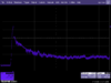
Here is a simple comparative analysis between device monitor data logging and an actual oscillogram. The scope input is smoothed over 5 sweeps, sin x/x interpolation, and bandwidth limited to 20mHZ. The function measured is simple voltage.....honestly not too bad for a consumer device. I wish there was some documentation on device monitors acquisition parameters (especially polling rate and how much smoothing is applied to the curve). P.S. This is a scripted 5 second "puff", and the plots are relatively time correlated


-
Here is some confirmation data of dna200 USB charge accuracies. The current source is a simple PSU set to 5v. I can confirm linear scaling in the charge current as the voltage is reduced.....the oscillogram is of the USB data lines (floating) int a FET probe, on the LeCroy. I repeated numerous fault conditions in both the data and power lines and there was no erratic behavior to mention. Current always capped out at around 1 amp. Shorting data lines lead to no erratic current spikes either. The discrepancy between OSD and DMM is USB cable losses. I purposely used the lowest quality USB cable I could find, so 20/30mA losses along the cable seems about right. Hope this information is useful for some. At the least it shows a large degree of confidence in evolv dna200 USB charge capabilities and controller......kudos evolv for building some decent BMS.....

-
-
Is there a way to zoom on the graph/curve? Right click seems to be working to enter a fixed value (thanks, been looking for that for a while now)... As far as being normalized, I am assuming they are normalized against the curve....is there a specific formula to follow there? Or just business as usual? I do have min max defined and the dna200 is without doubt right on target.....overshoot on our 0.5mm wire (built a full cal profile for it some days ago) was only around 4 deg F. Having the median ranges out to a 10/12 bit range should be adequate....will report back after I get some finer numbers into the scale....
-
I agree with Macz and also there is at least one titanium vendor who stated that he was going to have specific values for their wire. It would be in the end if all wire vendors do this.[/QUOTE] we are already working on it, but evolv needs to add granularity to the curves in eScribe....the 0.1 ohm incremental are not fine enough to get tight cals....
-
I traced the non linear current reduction problems in the test to a fault in the PSU. I terminated the data lines coming from the dna200 into the front end of the scope (through a FET probe) and the logic level seems to be correct, even under a fault condition.....I don't need to see packets, just want to see if any logic level faults can drive the dna200 to pull some oddball current spike.....so far everything is looking very good.....on screen vs device monitor vs my test loop only show a 2mA sDEV....data lines 24mV.....I can't seem to break it with a fault yet.....so I am moving it over to a sacrificial laptop....I built the interrupted USB cable we had talked about.....so I can take some metrics at any point in the USB line, and from both ends of the host/slave..... I have to say i am very impressed with the overall accuracy and safety in the dna200 charging....I have a few minor software gripes, but the hardware is looking very solid....I am gaining a lot of confidence in using USB as the primary charge method, with a fixed pack in the mod....I am seeing all the benefits that come with this approach, with none of the problems that other controllers have had (such as not living up to industry ratings or safety standards). You really don't want to play dice with a 30c 2200maH li-Po....the BMS on this early board is pretty good
-
idle time up to 60 seconds and active time bumped back up to 10 seconds, and still working fine.....it was failing to switch over, with these exact settings before *scratches head* *shrugs* I'll knock this one off the list and put it to bed....all is well ATM. I am experiencing some VERY strange behavior when using a dedicated PSU as charge input though....at 5v everything is just fine, but as soon as I dip below 4.8v things go haywire.....I will start a new thread on that subject, and include a video demo of the activity....PSU is not switching over to any kind of CC operation, BUT the current draw is very erratic....I'll get some data up as soon as I confirm there is no issue in the test loop.....to confirm the data lines are not active....I am assuming data lines in USB are 3.3v logic signals? I will hook up another external PSU and try to simulate some logic inits, and throw it up on the scope and see what I can see....I knew that eye diagram would be useful one day or another
-
idle time up to 30 seconds and still working fine....switching over to charge display after 30 seconds (timed it) and still showing stats correctly in device monitor, dna200 display and my external test gear....current draw is accurate (minus cabling losses)
-
ok this might be a potential bug.....I just set the idle time to 10 seconds and it's catching now....I see charge stats onscreen AND via device monitor, and via my eternal test jig correlates those numbers....let me start ramping up idle times again and see where it stops behaving correctly....I did reload eScribe etc....will report back if the issue crops up again.... Thanks for the feedback @protovapor I can scratch this issue off the list for now....
-
No, brightness was set on 50% for that scenario..... I am going to try and reload the entire eScribe suite and FW......I am very puzzled why my unit won't go into charge display while connected, and another will.....
-
[QUOTE=protovapor][QUOTE=SSV][QUOTE=John] There isn't a way to force charge display, but you can put charge parameters on the main display if you're interested. [/QUOTE] John seems to be confirming what my test board is doing....@protovapor [/QUOTE] There is no command to immediately make it switch to that mode, however it will switch normally based on your time parameters. To my understanding, it switches after "active time" and "idle time" settings both elapse. If you set both of those to a very short time you can sort of get it to switch on demand.[/QUOTE] mine is not doing that.....can you test/verify that on one of your units? If my test unit is connected to eScribe, it doesn't switch over to charge display at any point....I did play with times and nothing....*scratches head*
-
ahhhh.....is the load purely capacitive (no ballast resistors on the input stage)? that def quenches my concerns....(I mean obviously any load is resistive, but if it's = to free air I see your point)
-
[QUOTE=John] There isn't a way to force charge display, but you can put charge parameters on the main display if you're interested. [/QUOTE] John seems to be confirming what my test board is doing....@protovapor
-
running latest versions of both eScribe and board FW and it my unit does not go into charge display mode when connected....the unit will charge, but display does not change over to secondary charge mode parameters....however it does when I disconnect from eScribe
-
Will do, I'll grab some anemic "charge only" cables and see if I can pop something...I'll use your suggested method (just strip back the cable and put it into DC (I) side of the DMM). As far as burdens, I am referring to the burden voltage of the DMM itself....which is why I typically try and use the shunt into DCv.....but again I am typically measuring uA and such. Probably not at all relevant to this test, but I do ALWAYS try to null any external uncertainty from the DUT. http://zone.ni.com/reference/en-XX/help/370384N-01/dmm/burden_voltage/ http://www.fluke.com/fluke/uses/comunidad/fluke-news-plus/articlecategories/electrical/burdenvoltage ^----again probably overkill for this scenario, but I am creature of habit.....obviously the device monitor and dna200 screen are only reading out to mA, and I am looking at uA....but I do need to justify the price of those least significant digits on my bench meter... I'll try running the inputs at both 10mOhm and 10gOhm and see if I can account for any uncertainty there... P.S. having the ability to force charge mode in eScribe could be VERY useful....I'm sure that is low on the priority list right now, but would be nice to test screen layouts and correlation to external measurements + device monitor....


