

Mad Scientist
-
Posts
247 -
Joined
-
Last visited
-
Days Won
1
Content Type
Profiles
Forums
Downloads
Everything posted by Mad Scientist
-
Solder type at contact points?
Mad Scientist replied to Podunk Steam's topic in Installation and Assembly
No worries. 12 or 14, either way still powers a good vape lol. -
Solder type at contact points?
Mad Scientist replied to Podunk Steam's topic in Installation and Assembly
Irrelevant because the collar won't. If you want to go with 12, drill the collar to fit 12 wire. Strip enough insulation so the collar and spring will slide down far enough to give clearance to solder the pin. Solder with a high watt soldering iron (I use 150 watt). Assemble the pin, spring and collar. Heat shrink over the bit of exposed wire under the collar. Done. Some heat will transfer from wire to collar to spring. It is not enough to anneal the spring. Cheers. -
Solder type at contact points?
Mad Scientist replied to Podunk Steam's topic in Installation and Assembly
The spring rests on the collar that slides down the wire about 7 mm or so. Thermal contact between spring and wire is minimal. Beyond that, annealing temp of even high carbon steel is around 1,400 F. Solder melts under 400 F. Unless you solder with a torch, spring will be just fine. -
It will last about a week and take about 24 hours to recharge.
-
feature request auto select
Mad Scientist replied to shzrocka's topic in EScribe, Software and Firmware
I agree except when swapping hot attys for comparisons back and forth. Can be handy to lock it then override with cold res of each. -
Well I know you guys at evolv are very busy but (always a but, right lol) was wondering if consideration could be given to have an option to show the values decaying on the graph in device manager. I'd like to be able to see temp decay after firing -- basically just leave the graph, well, graphing. I realize this will use some power to read the resistance but I'd like the option if it's an easy one. Thanks very much -- even if you can't get to it or don't think it's a good idea, I do very much appreciate the unbelievable level of responsiveness you evolv guys have demonstrated.
-
feature request auto select
Mad Scientist replied to shzrocka's topic in EScribe, Software and Firmware
You could maybe try resistance locking in each profile if you want it to work that way. With a separate resistance locked profile for each atty, it won't ask new coil. Cheers. -
Solder type at contact points?
Mad Scientist replied to Podunk Steam's topic in Installation and Assembly
I've used 12 stranded and fine stranded (and the fine stranded is a challenge). Your idea works perfect for that too. It takes a bit of care and a hot iron (I use 150 watt iron for this) but it definitely works. There is no room for the insulation after drilling, just the wire. A bit of heat shrink over the exposed wire after soldering and assembly finishes the job. -
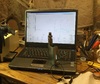
Wiring was mercifully very simple. The battery sled has the middle tab exposed on top to add a wire for the tap. I used a piece of wirewrap wire threaded behind the battery sled to connect that tap to the DNA 200 (hope it's thick enough -- that's all that would fit -- all it carries is a bit of balancing current so should be OK). Using the existing up / down buttons was also easy once I figured out how to support the little daughter board with the original mother board removed. The existing buttons use a common return path but that's OK because the up- and down- are common on the DNA 200. Making the fire bar work properly and fit exactly back where it was as stock was a project. The trick was a lot of milling of the original plastic sled and fabricating little supports for the board. The existing fire bar setup pressed two buttons mounted down the middle of the original motherboard. The whole fire bar assembly originally mounted through two holes in the middle of the motherboard. Uh oh, DNA 200 doesn't have two holes down its middle and doesn't have two fire switches where they belong either. The entire assembly had to be "re-engineered" to fit, to move and to press the DNA 200 fire button but not press on anything else. Installing the VT 510 was also a little involved. The external threads weren't long enough so the underneath area of the xcube top plate had to be milled out. To sum up, if I had it to do over again, this would not have been my first choice for a retrofit. It was a lot of work. Now that it actually works, it was worth it lol.
-
I put an Xcube 2 that I hated under the knife (under the carbide actually lol). Now it lives on as a DNA 133. Oh, and that pack of smokes on the bench has been there since May, 2013 lol.
-
Did you check the ohm lock range in the mod tab? Default 25%? I know you didn't want more questions but is the 510 making good contact and have a solid connection to B-? I guess have to rule out the easy ones first. Mine definitely doesn't do that and haven't heard of a similar problem to date.
-
Solder type at contact points?
Mad Scientist replied to Podunk Steam's topic in Installation and Assembly
Someone, I think it was Vaping Bad, discovered the trick. Use a VT 510 and drill the hole in the brass cap at the bottom large enough for the wire to slide through. Strip enough insulation so the wire can move up and down in the cap and there's enough room to solder on the pin. After soldering on the little pin and reassembly, use some heat shrink to cover any exposed wire. -
Solder type at contact points?
Mad Scientist replied to Podunk Steam's topic in Installation and Assembly
Lol. You're toothpick is thinking in the right direction. The resistivity of copper wire per meter almost doubles from 12 AWG to 14 AWG. Might have some more mileage there. For the couple inches we use to connect to the 510 likely doesn't matter but there is a difference. -
Solder type at contact points?
Mad Scientist replied to Podunk Steam's topic in Installation and Assembly
True, the volume resistivity of silver solder over standard eutectic lead bearing solder ranges from 15% to 25% less resistance for a given volume depending on the exact alloys used, etc. But if you really want to go there, you also have to consider percentage of what. Volume resistivity of typical silver solder is around 1.03E-5 ohm-cm. Thats about ten millions of an ohm in a one cm cube or 100 millionths of an ohm in a one mm cube. Even if the joint was only 1 mm square of solid solder, the difference between the types is like 15 nano-ohms. I just can't see it making much difference when we are basically struggling to measure ones and tens of milli-ohms. It can't hurt to use a silver bearing solder but plain solder is fine . . . and a lot easier to work with lol. -
The best I've come up with so far is to lock the resistance and override it to its measured cold value. Then it does not ask. That shuts off any refinement but as long as the measured override is accurate, performance is just as perfect as always. Maybe down the road there will be a serial command for up and down button press.
-
For the benefit of anyone else reading this thread whose mind works the way mine does (scary thought lol) the numbers referred to are not pin numbers, they are cell numbers. Bridging 2 and 3 means cell 2 and 3 at pins 3 and 4, etc. Ground doesn't seem to be worthy of a number. Luckily the board is very forgiving of screwing that up (guess how I know lol). My latest DNA 133 creation is now done except for the 510. Hope to finish that up tonight. Pics will be forthcoming.
-
It's not so much the temperature but the heat. I use a 150 watt iron for the big stuff and on 12 AWG stranded that's barely enough. If you have enough heat and can get the solder to flow quickly, the risk of overheating anything is actually reduced.
-
Hi James, Version 1.0.32 if that helps. Thanks.
-
Running escribe on Windows XP, Service Pack 3, Gateway laptop (yes, I remain in the stone ages of Windows lol). The graph in Device Manager "flashes" to black at a rate of about 2 Hz. Seems to be related to updating the on screen data. I also have to pause the graph to be able to enter anything (the flashing obscures the pop up boxes). It has always done this with each version of escribe but it's really starting to bother me so I thought I'd ask. Everything else seems to work with no issues at all. Anyone else having this problem? Any solutions? Thanks.
-
Crickets?
-
Im not sure if this is exactly what you're looking for but Steam Engine has DNA 200 .csv files for various wire types. http://www.steam-engine.org/wirewiz.asp Go to wire wizard, select your wire type and hit DNA 200 in the tabs along the left of the graph box in the upper right. Download the .csv file and then use that for "custom" wire type in escribe. Works like a charm lol.
-
This is the first commercially produced DNA 200 mod that as soon as I saw it I knew I have to have one. @Rocky2015, when and where will they be available? I think you guys have a big winner with this one.
-
Feature Suggestion: External status/control interface
Mad Scientist replied to wolrah's topic in DNA 200 and 250
Hi Wolrah, I think you can already do exactly what you're talking about using the existing USB HID on the DNA 200. Numerous PIC chips have USB on chip and it would seem (?) easy enough to use a PIC as a virtually universal interface translator for whatever you have in mind. With the existing serial commands disclosed so far, the user interface save the fire button (and up/down buttons as discussed below) is available for full customization without needing the stock screen or button hardware. The only things missing (that I've found so far) are the button press commands. We need a way to tell it "up" or "down" without actually pressing a button. I've asked if there is some way to do that over in the software forum but no replies yet. My hope is it's something easy enough to implement that we get it as a feature in the serial command set in the near future. It could be done with a couple of the open collector outputs on a PIC to the switch pads on the board, but that's sort of a wasteful hardware solution to what appears to be a simple command interface capability better done in software. I'd be interested to hear of any progress you make. My project focus right now is on a relatively large set of isolated very low thermal mass thermocouples for a set of experiments I dreamed up years ago but now with more modern vaping hardware readily available can finally implement. I'm also futzing around with a buttonless mod idea. The next project after that will be going wireless with the DNA 200 to PC (and hopefully by the time I get to it, Evolv will have already come out with their Bluetooth version of the board and escribe app for tablets lol). -
Is there a serial command or other method to respond to the new coil question in escribe without pressing a button on the board? Maybe just "up" and "down" serial commands?
-
This one might do you better. https://www.fasttech.com/products/3177800
