CriticoolHit
-
Posts
6 -
Joined
-
Last visited
Content Type
Profiles
Forums
Downloads
Everything posted by CriticoolHit
-
help Did I bungle it? I probably bungled it (voltage issue)
CriticoolHit replied to CriticoolHit's topic in Modders' Forum
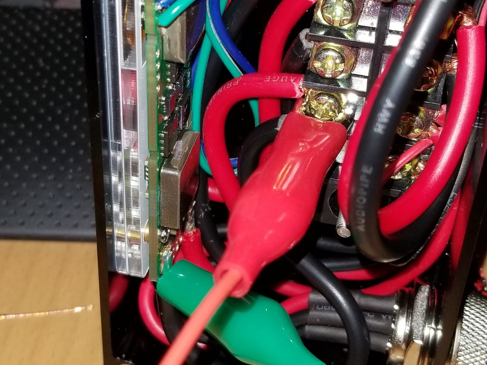
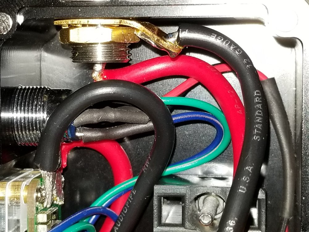
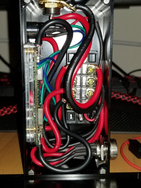
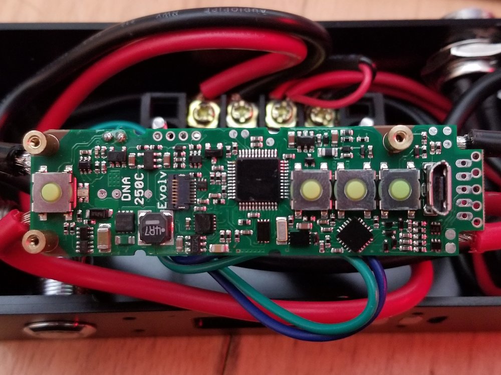
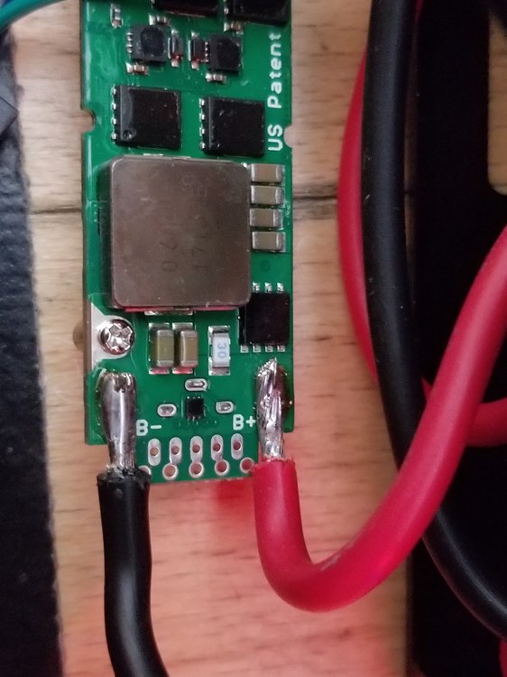
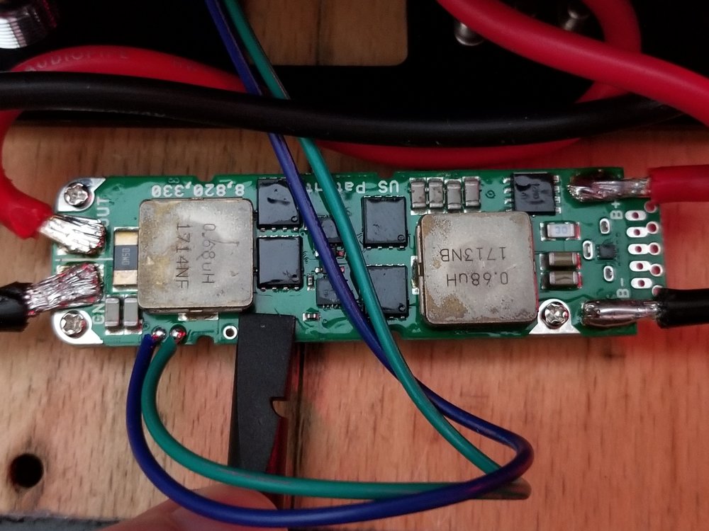
Bummer! That's what i was going to ask next. If there was a dev-mode beyond just "research" that would allow me to adjust the offset but if it is done via bandgap output that's a no go. Chances are I cooked a diode while soldering the pads, or it came lame from the barn (I like this one because it's not my fault lol). I attached a couple of pictures of my board and soldering efforts. Things are "close" and I know components destroyed by head don't always present visually but the board still looks 'good'. So this is probably where this ends. Ill engage in a conversation with stealthvapes regarding an RMA but given my desire to tinker ill probably just order another one direct from evolv anyways. This one still works 'fine' after all. Thank you everyone who contributed and offered solutions. I am glad the rave-reviews of evolve support are well founded.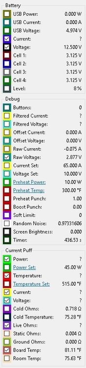
-
help Did I bungle it? I probably bungled it (voltage issue)
CriticoolHit replied to CriticoolHit's topic in Modders' Forum
Thanks for the tip. I just put in a ticket referencing this thread and boiling the issue down to something less painful to endure read. -
help Did I bungle it? I probably bungled it (voltage issue)
CriticoolHit replied to CriticoolHit's topic in Modders' Forum
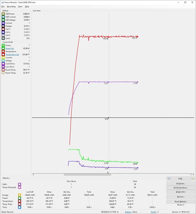
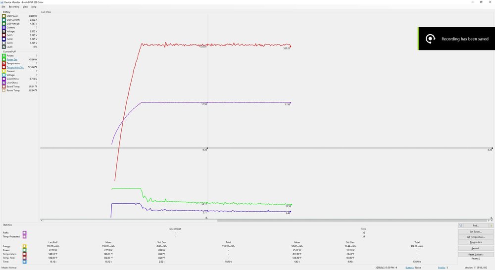
Hey Craig. So I gave that a shot. Uninstalled my windows version of EScribe, deleted all potential caches and profiles. Installed the INT version of EScribe, and subsequently the latest INT flash to the chip and then of course a factory reset. Firmware Version: 1.1 SP33.2 INT Revision Code: 311103398 USB Vendor ID: 268B USB Product ID: 0419 USB Product Version: 3.0 Unfortunately when in 12v power supply mode the device still reports 9.38 volts. --Bummer I guess at the end of the day this is nothing more than an inconvenience as long as its still safe to use... EDIT: Update: Given the 3 volt drop. And the apparent current draw matching what it says on the screen rather than what I know is on the pad (leading me to believe there is actually a failure on-board) I set the device to 15v 4s. The Graphs are now at least in line with the napkin math I did for projected current draw before I started.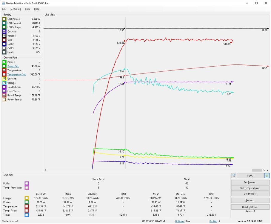
-
help Did I bungle it? I probably bungled it (voltage issue)
CriticoolHit replied to CriticoolHit's topic in Modders' Forum
I completely agree that post is horrible and long because of the pics. I just missed the edit deadline lol. Solid idea, hadn't tried it. It reads 6.37 volts when set to 9 volts. Exactly 3 volts below input. Which is what 9.38 was to the 12.38 volts I was running to account for Vsag during firing, exactly 3 volts low. While I don't have a picture of that I was able to get my witches hat probes from my o-scope and hook it securely so as to make contact with the pad and cable. Its a solid connection. (as we see from above it's likely not a connection issue). That Meanwell supply doesn't sweat this. I fired a 100 watt load into a ceramic resistor for about 20 seconds and it was rock solid at 0.16 sag (not bad for these supplies). It didn't budge at the 45 watts I asked of it for a true load heh. I gave it a visual inspection and connected it to a breadboard to test functionality out of the box. (didn't think to check this) After that I used fine tip to add the remote firing wire, put it in the sled and treated it with great care. I just disassembled it again, (thanking myself for putting in that terminal block) the board itself looks day-1 new sans the resin from my soldering. I inspected the ICs nearest the pads for burning and the like and everything looks good. I didn't rest the iron on a capacitor after all lol (phew) FW: Yeah, pretty sure when I first fired up escribe there was a message saying there was a newer firmware version and I let it go first thing. Firmware Version: 1.1 SP33.2 US Revision Code: 311103395 USB Vendor ID: 268B USB Product ID: 0419 USB Product Version: 3.0 If it's just a reporting issue or mis-calibration (which it seems to be as it feels identical to my other chip at the same settings) then ill just keep this one for play and buy another for the final revision... One without a terminal strip. Thanks. Crit. (the final one will probably still have a terminal strip heh) -
help Did I bungle it? I probably bungled it (voltage issue)
CriticoolHit replied to CriticoolHit's topic in Modders' Forum
I do indeed have that setting selected. Which is why I thought it quite strange the diagnostic was reporting 3 cells. My apologies about the post length. When i attached the images i did not expect them to expand and just be added to the post like that. I was in the process of going back and adding hyperlinked permanent imgur links to clean it up. EDIT: Though it seems I can no longer edit that post. If you can, delete all the pictures and replace them with one clean link to the album at the bottom: https://imgur.com/a/tiIL1B6 Thanks. -
help Did I bungle it? I probably bungled it (voltage issue)
CriticoolHit posted a topic in Modders' Forum
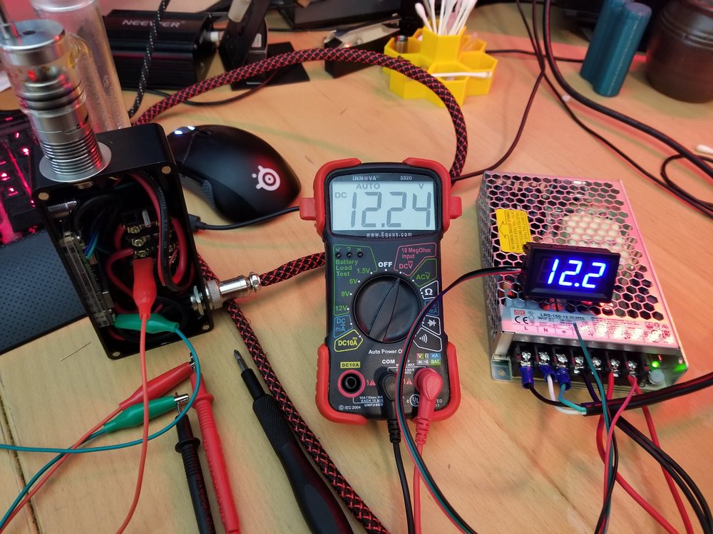
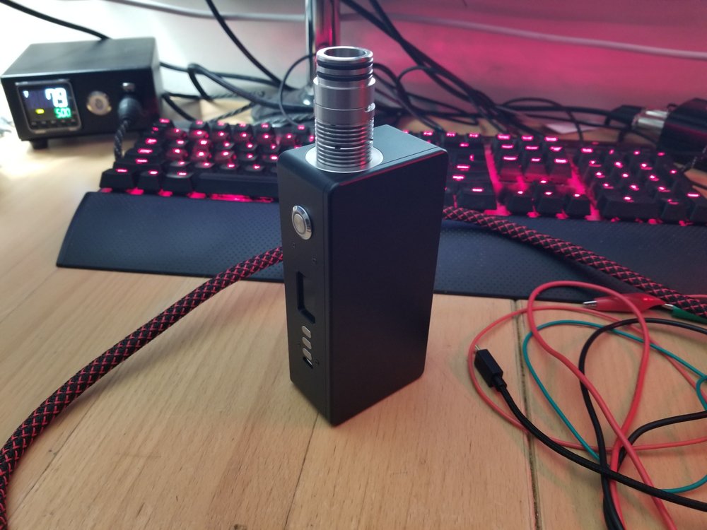
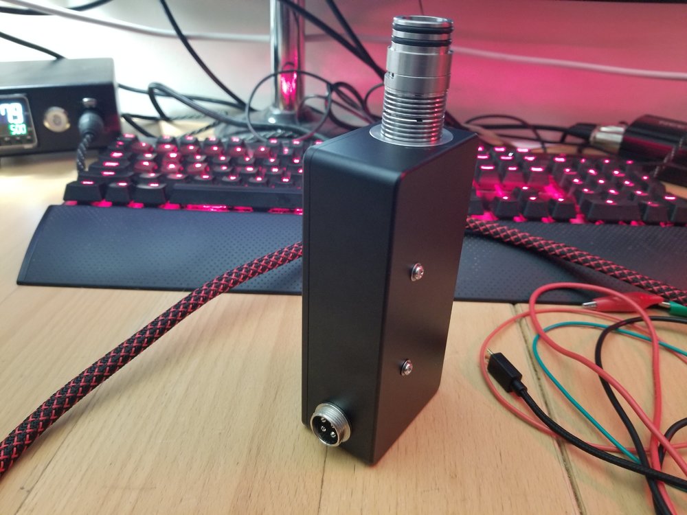
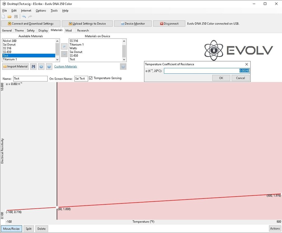
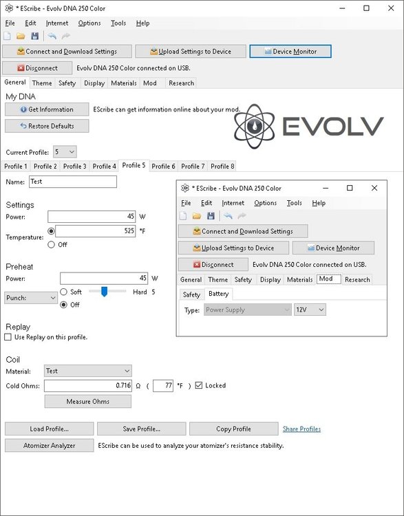
Alright. So I 'read' the manual. And I googled around for a while hunting down others voltage issues but everything I find is battery related... I think my case might be a little more specific. So let me preface this by saying i like to tinker. So decisions were made to ensure that I could change things around often. This should take care of things liked "dude that is a-lot of wire" and "Why in the f**k do you need a terminal strip". Since I am also a fan of over-building everything we can avoid things like "Bro; but it's barely 4 amps!" or even the occasional "you can get cheaper better built ones online". It's just a simple passthrough box (screenshots attached) with a terminal strip to terminate all connections. Easy to take apart and put back together and modify. This is far from its final form, just a proof. I'm coming over from a GENE chip (the drag) because it's time to leave batteries behind. I got the 250c because I can't help myself, easy enough to justify with a "just in case" --right? I got the giant case because I have big clumsy hands and limited to moderate patience when the lower back starts to ache from hunching over to work on tiny things in smaller places. The power supply is a genuine Meanwell LRS-150. Will be connected to a LRS-350 for the full 30 amps when in final use. So that I can use all of 45 of those 350 watts... That out of the way lets talk about 9.38 volts. And why the DNA chip seems to think that's what its getting. * Plug in brand new chip. Apply 12.25v. * Plug in USB (5v). * Download and push latest firmware and reset * Generate custom material profile based on COMPLETELY TRUSTWORTHY(tm) Reddit information. (screenshot attached) --- TC/r value. To: 0.00240 --- Temp sensing (of course) * Set the custom values in the profile. (Screenshot attached) --- 45 watts --- No preheat --- Temp cap 525 --- No replay --- Locked resistance based on new coil 24 hours at room temp. * Push to device * Satisfaction (until i check the diagnostics) Wiring is 2 runs of 16 gauge for power and ground from the PSU to the block. I would love to have used 2 runs of 12 but the aviation connectors wouldn't have it. Speakon for V2 if this proof of concept works. 12 gauge for everything else. Seriously disappointed in the stock pad-soldering solution for a supposed 400 watts. That's it really. Thing performs flawlessly at these settings and feels exactly like my GENE chips at the same (converted) settings. I just don't understand why the chip is reading 9.38 volts. Doesn't behave like its under powered, still need to get my shunt and ammeter in the loop to see whats up in that regard. I understand every time you add a link in the chain, another connection, another length of wire, another terminal and so on you add resistance which can effect voltage at high power levels. I scuff-buff-n-clean all my connection points and solder joints. Clean all conformal coating off and pre-tin the pads and wires. I also fully admit I solder with the dexterity of a ham-fisted gorilla on methamphetamine. I have tested every link in the chain repeatedly with a multitude of multiple multi meters and displays of varying known offsets. I know beyond a shadow of the doubt I had the 3rd time I de-soldered EVERYTHING and re-soldered it; those pads are absolutely mechanically and electrically connected. Thanks in advance. Hope I just dun-goofd' a setting somewhere. I'm worried I cooked it during some of that professional soldering..... Had fun writing this up and getting the screen shots though 😉 -Crit (bonus points for why it thinks it has 3 cells when i didn't even so much as solder on the connector)