

mamu
-
Posts
21 -
Joined
-
Last visited
Content Type
Profiles
Forums
Downloads
Everything posted by mamu
-
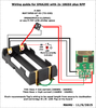
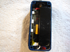
Wiring breadboarded, tested, and good to go - no damage to board or batt meltdown if the batts are put in backwards. This RPP wiring with P-FET gives complete protection for the stoopids. Red LED reverse polarity indicator lights if both batts are inserted backwards. Without the LED, there is no indication that the batts are in backwards - the DNA200 + screen simply will not work - so you're on your own to figure out the something stoopid you did lol. The LED lights only if both batts are put in backwards - does not light if only one batt is inserted backwards - there is no indicator to let you know the batts are in parallel. Note: if batts are in backwards and you connect the board to USB, there is no damage or issues if attempting to charge while the batts are reversed. However, the board/screen functions except for firing - if you attempt to fire the mod, you'll get the "Check Atomizer" message if no atty is attached, or "Check Battery" message if an atty is attached. You'll also note in this situation there is no batt indicator bar showing on the screen. Wiring guide:
-
Mamu Dna 200 Faceplate+Dna200 installed depth
mamu replied to Odrama's topic in Installation and Assembly
lol you PM'd me for this too. Check your PMs. -
If you have CAD skills, design a button set, upload to shapeways, then choose metal - they have stainless steel, bronze, gold, etc. About $10 or so for a set. I did that with my faceplate and mods. I buy as a set and then dremel off the supports - is the cheapest way to go, else you can buy the individual buttons but that is a more expensive way to go. https://www.shapeways.com/product/E65VJ388Y/dna200-complete-button-set-round-top?li=shop-results&optionId=57463209

-
What battery are you using/planning to use?
mamu replied to vaporlips's topic in Batteries and Charging
I stand corrected then. A modder friend asked and was told it wasn't doable so was relaying what he was told. -
What battery are you using/planning to use?
mamu replied to vaporlips's topic in Batteries and Charging
Not doable. Escribe can't monitor six 3.7v cells, but more importantly the DNA200 can only charge and balance three 3.7v cells. -
-
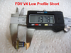
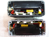
alee132 - It's doable to fit the 950, just a lot of dremel work goes into it. Both inside long edges need half mm or so dremeled off to widen the width and the lower corner post needs removed. Another option, but not sure one I would recommend, is removing the white plastic underneath the heat shrink tubing that wraps around the 950 lipo pack as that takes up about a mm, but you still may need to dremel some along the inside edges to widen the width a bit. Also, the Varitube 510 connector is 2mm shorter than the FDV V4 shorty. Here's my build with the 950 lipo pack. Here's the build with a Fullymax 900mAh (top) and MaxAmps 800mAh (bottom).
-
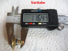
I'm using the recommended size that the datasheet lists - 18AWG for input and 14AWG for output. I was working with the Turnigy nano-tech 950 lipo pack build with the 1590A and faceplate this week, and it will not fit without some major dremel work to the case along the side wall and also removing the lower corner post unless you offset the 510 to the side. The packs I have are 21mm in depth, not 20mm as advertised, and with the way the case slants inward from front to back it's a definite no go without some major dremel work. The case needs just a mm more in width. It's a lot of work to dremel out the case to widen it a mm more to fit the lipo pack and also to remove the lower corner post if you want the 510 centered. The MaxAmps 800mAh 40C and FullyMax 900mAh 30C do fit without needing dremel work except for the faceplate cutout and 510 connector hole.
-
I used 56mm (flat width) - it's what I have on hand and close enough to the calculated width that it form fits the pack aok when shrunk. The equation is circumference / 2 + 5mm. The circumference of the 950 pack is 90mm. 90/2 = 45 + 5 = 50mm
-
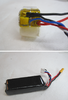
If you're familiar with soldering and working with lipos, it's fairly simple to replace the 20AWG with 18AWG with the Turnigy nano-tech 950mAh 25C lipo pack as the +/- wires are easily accessible. Here's one I did... just make sure you always have the lead you're not working with covered and protected. Then heat shrink the pack when you're done.
-
What battery are you using/planning to use?
mamu replied to vaporlips's topic in Batteries and Charging
I'm sorry, I forgot to click the Subscribe to this thread button so to get notifications. I'm getting the same performance (meaning I can't tell any difference) as the 3S Fullymax 900mAh 30C and MaxAmps 800mAh 40C. But then, I'm a wush lol. Running 0.08 ohm, TC, 20W, and with preheat burst at 25W and punch at 1. Those running full tilt may notice a difference between the lipo packs. Should fit as has similar dimensions, just a mm more width than what is being used in the beta mod. The 3 that I found that fit and with essentially the same dimensions are: MaxAmps 800mAh 30C Turnigy nano-tech 950mAh 25C Fullymax 900mAh 30C (this is what is currently in my beta mod) -
What battery are you using/planning to use?
mamu replied to vaporlips's topic in Batteries and Charging
I'm getting a day and then some of vape runtime using the beta mod with a FullyMax 900mAh 30C lipo pack, as well as a DNA200 mod using MaxAmps 800mAh 40C lipo pack, before needing a charge. Running 20W, 0.09 coil, TC, and I'm a fairly constant vaper. These are the batts I have and testing (all 3S): FullyMax 900mAh, 30C MaxAmps 800mAh 40C Turnigy nano-tech 950mAh, 25C Turnigy nano-tech 1300mAh, 25C MaxAmps 1300mAh, 100C MaxAmps 1800mAh, 100C -
You can look at this way, Mike. If the onboard fuse blows you're gonna be getting that mod back from the user anyway to troubleshoot it for why the fuse popped and more than likely replace the lipo pack. I used a hot air gun to remove the blown fuse and just a regular soldering iron tip to solder a new one on. It was a pita, but not a major biggie to get it done. My experience with removing and soldering the cable end on the DNA regular screen def comes in handy here.
-
The problem with having a fuse with an Ihold rated lower than the max input current of the DNA (<23A) is that if the user runs the DNA200 at or close to max input there may be inadvertent tripping, or a pre-trip phase where the internal resistance of the fuse rises and it gets very warm. This increased circuit resistance would interfere with the DNA200 correctly working with a subsequent weak battery message even with fully charged batteries. The DNA200 would see it as the batteries not capable of the current needed.
-
Well, Evolv is turning the meaning of mAh on its toes lol. We traditionally think of series batts where the voltage is multiplied while the mAh of the pack stays the same. Meaning 3S 1000mAh 3.7v batts would have a nominal voltage of 11.1v, while the capacity of the pack stays at 1000mAh. The DNA200 runs on the energy density of the batts with x amount of watts in, x amount of watts out, treating each cell as individual cells, so you effectively get 3x the capacity of the 3S batts. Not exactly 3x, but pretty darn close. Meaning the 3S 1000mAh batts will give you close to 3000mAh - which significantly increases the vape runtime before needing a charge.
-
You'll get a longer vape runtime with the 3S 900/1000 mAh lipo pack vs the single 18650 2000mAh. With the way the DNA200 uses batteries, you can essentially triple the mAh of the pack. So with 3S 900mAh, you'll have approximately 2700mAh and with the 1000mAh, you'll have approximately 3000mAh.
-
Thanks Mamu, I have this one http://www.digikey.com/product-search/en?vendor=0&keywords=MHP-TA15-9-77 instead of the link above. I used those for my previous DNA40 lipo build Specs shows the same, just parts number are different. Will this work?[/QUOTE] Yes, those are the same, but pop at a lower temp. Also, they fry fairly easily if applying too much heat when soldering, whereas the 90 don't. But, these are no go for the DNA200 as the max volt they can handle is 9v. I use them for the DNA40 which max volt is 4.2v.
-
oh wait... the fuses I linked are good for 9v max, so no can do for the DNA200. Will have to find an alternative.
-
If I were to add an external fuse so I would never have to replace the onboard fuse, I would use 2x in parallel these 15A TE fuses soldered directly to the positive lead of the lipo pack: http://www.digikey.com/product-detail/en/RF3038-000/RF3038-000-ND/3748599 Tiny so they don't take up much space and pop uber fast.
-
The lipo pack Justin linked to is used in the Opus 200. It is not the one used in the beta mod.
-
Mike - the onboard fuse works great for protection and pops uber fast. I tested it last week and no damage to the board or batteries. If the fuse pops though, will need replaced. Replacing that teeny tiny fuse is a pita lol. You can visually see if the fuse is blown as the top covering melts off - intact = green; blown = white - which is good for troubleshooting. I don't see a reason to add another one since the onboard fuse is already essentially at the battery level, unless you want to add another one so you'll never have to replace the onboard one as I said it's a pita to replace.


