

vapealone
-
Posts
33 -
Joined
-
Last visited
Never
Content Type
Profiles
Forums
Downloads
Everything posted by vapealone
-
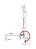
BTW, I have made my mini monster (38mm x 50mm x 85mm) from scratches but you can buy (or will be able to buy soon) small, professionally designed 3 x 18650 mod for yourself if you wish e.g. the Wismec Reuleaux with dimensions not much different from the Lavabox (Reuleaux : 40mm x 50mm x 84mm vs Lavabox: 28.15mm x 46.19mm x 94.87mm)
-
For I don't do high power I figured that multiple Li-Ions and their extended capacity would suit me better even with its significant voltage drops And with this mod, my whole thing about the cutoff is really just a bonus feature. One day I forgot to charge it during the night and when it took me home on the next day after work it annoyed the hell out of me with the power limitation and still had plenty of charge when I have put it on the charger I don't want to limit myself vaping I want the board to simply cut it off and doesn't allow me annoying myself
-
I agree Mad but I am talking about Li-Ion that is significantly different AFAIK
-
I am happy that you think my proposed approach would be a bit more convenient than the present one. However, I don't completely agree with your point regarding to the 3.5V resting threshold for I think that it depends on the load and the batts IR and it can easily be more than just a handful of puffs. E.g.: my batts have ~15% left around 3.5 restV when rest cutoff is set to ~3.25-3.3V (should check the recorded csv and probably will later) this 15% means 28.4Wh x 0.15= 4.26Wh=255.6Wm=15,336Ws=15,336Ws/(25W mean power x 2s mean puff) = 306 puffs for me (if my maths holds And I wouldn't call it insignificant for it is more than 40% of the overall capacity of Evolv's 900mAh reference mod Of course, for Li-Ion it can indeed be a lot smaller should I set my Wattage higher. And that is why I would like to have a bulletproof battery management system that looking after me regardless of my power settings and doesn't cost me precious Whs and/or neither ruins my last Whs if not necessary.
-
@bmclaurin Thanks to your answers but I really don't get your point even though I happened to hit the record button and checked the result including how the soft cutoff works. Again, it is not for maximize puffs it is for optimize the discharge. Let me give you an example. Example #1 Let the target idle/rest voltage is 3.3V for the sake of battery longevity. Voltage under load is not a real issue as long as it stays above min 2.7V and the battery can recover to 3.3V Let the voltage drop 0.1V for every 50W load (means 0.4 for 200w) just for the sake of the argument. It means that I should set my soft cutoff to 3.2V for 50W, 3.1 for 100W, 3.0 for 150W etc. And if I do it AND stop vaping when I hit the weak battery warning I will get the nice and safe 3.3V rest/idle And that is my point. That I would need different cutoff values for different target drains and would need to stop vaping when hitting the weak battery otherwise I would drain my batteries below target. Or: I set my cutoff to 3.3V and completely ruin my own vape in the 3.4-3.7 idle/rest V range (depending on the power setting) by the soft cutoff regulation. Meanwhile with two values I can set my idle/rest and under load separately fully covering all the wattage (voltage drops) range AND fully eliminate any accidental over drain AND fully eliminate any unnecessary output reduction because the board thinks (wrongly) that my battery is weak: Example #2 Target idle/rest voltage: 3.3V Target min under load voltage: 3.0V Desired operation: If target idle/rest voltage <3.3V no firing at all but low battery warning only If target voltage>3.3V firing as per now protected and limited if needed by the soft cutoff Working in the low volts: As long as I don't hit any of the thresholds the mod would fire as per normal. In this example, below 3.4V idle/rest and above 150W setting I would get weak battery warning and power reduction for the last few puffs which is acceptable. (or if not, I would reduce soft cutoff to 2.9V ) Worst case scenario: V rest/idle: 3.30..01V, power setting 200W and firing. The mod would fire indeed and depending on the batteries even up to 200W more likely below though. Either way, after this very last puff it would cut off nicely and the voltage would recover pretty close to 3.3V Bottom line: Trying to obtain given target rest voltage for Li-Ion with a single under load value (soft cutoff) is not optimal IMO. P.S.: Again, it is not crucial at all. You can save your batteries with the present setting options too. It is all about the quality of the vape when you are getting low on charge without getting the soft cutoff engages unnecessarily.
-
I don't want to squeeze everithing out. On the contrary. I want to optimize the draw. What this curve is doesn't show is the idle voltage it goes back. You might want to Google a pulse discharge curve. You will find a few. What is interesting in the chart you attached is how it starts. The higher the draw the bigger the initial drop. But if you cut the drain the difference between the idle voltage will be way smaller than the difference between the voltage under load. And that is the point.E.g. in this chart initial drop goes up to cca 0.4V down to 3.8. But if you cut the load after a few sec it would go back above 4 probably pretty close to 4.2.In other word it doesn't mean that you drained your battery to 3.8V. Besides, if you check my battery analyzer settings you would find that my amp draw was around 5A which is not outrageous for a good Li-Ion
-
I have built and use a 3 x 18650 mod as an ADV and would welcome a Li-Ion Battery option in the battery drop down with 2 different cutoff voltage settings: Cell Soft Cutoff: as it is now, for voltage value under loadCell Hard or Idle Cutoff: for a higher, idle (voltage w/o load) value My understanding is that: Li-Ion has a significant and drain dependent voltage drop (due to its internal resistance?) Under load voltage can go as low as 2.7V as long as the idle voltage goes back to 3V or above. For safety and longevity point of view I would like the board eliminating firing when idle voltage couldn't go back to or above 3.2-3.3V but I wouldn't mind if it goes down to 2.9-3V under load. ATM I can't really do this. If I set the soft cutoff to 3.2 I got weak battery warning (and reduced output) relatively early. If I set the soft cutoff to 3 or 2.9 the board won't prevent me to discharge my batts close to this numbers, would give the weak battery warning though. I admit that it is not some super crucial issue, especially with the 3 x LG HG2 I am using. I get an insane 28.4Wh out of them even if I play it super safe (w/ high soft cutoff settings). But with two values the Li-Ion discharge could be controlled pretty well regardless of the drain and the actual internal resistance without getting the annoying weak battery warning and power reduction unnecessarily. BTW, here is my discharge curve for 3 x LG HG2 3000 mAh batteries @ 50W w 3.09V soft cutoff. LGHG2-3cell@50W 3090mV SCutoff.txt (in txt format for csv is not supported by the page FYI: I have an external quick blow glass fuse in the circuit with unknown resistance therefore my curve is more likely a bit steeper than it should be.
-
I hope that in the meantime you have found the ideal solution. BTW, I was thinking a simple n channel fet solution with gate attached to the last (first? anyway the one is connected to B-) battery only. Source would be the (-) of this battery and drain would be B- on the board. If I read it right VGS would be + only (and circuit closed there) if the polarity is right and the dV is 3* V bat or there is no dv at all between B- and B+. It sounded promising but I was a bit worried about the extra load attached to 1 cell only and any unbalance it might result. Besides, it would cut off only the main circuit and I don't know if any unwanted potential difference on the charging tab would do any harm even with main ground cut or not. Not to mention that I didn't bother to look into the charging at all Therefore I went for a simple external quick blow fuse and hope for the best
-
Well, on my wavelength your board didn't read atomizer resistance w/o battery power plug connected and, strictly on this wavelength, kinda think that you couldn't continuously fire the mod up even on 1W settings when only charging cables attached Of course, it is possible that it works if you connect (-) for ground but don't connect (+) (modelling a blown fuse) I might try it one day. I want to hook up an external fuse anyway, so I can check when the replacement board is here (and find room for the extra fuse)
-
Well, like I have said, my hunting is over. I couldn't get any closer. If Evolv will check/it flex it when they get it back, so be it. But if it wasn't over, I would start from the other side The only thing I can tell for sure that AA can work. So I would look at this function first checking how it can possibly be powered up, which circuit(s) must be closed etc. Than check all the possible bridging ways/spots that can close it w/o fuse) Than check the circuits powered by USB close enough for some mechanical shorting if forced.... etc
-
I hear you, don't fully agree though I agree that there are too many blown fuses around and I haven't see rock solid evidences on modder failure or on anything else. It could be this or that or whatever. And that is exactly why I pushing on the option that the USB can short out some circuit if forced. It was a very 'lucky' find* and hard to mimic it for testing. I have already stopped experimenting with it as I don't want to deliberately damage neither the board board my cables. But it was a real, live short. The possible outcomes of this short or the actual location of it (on the board or in the male/female socket itself) is still unknown and no one really knowledgeable bothers to look at it. (John just explained normal conditions above that doesn't hold if you short out the designed way) I have actually planned to pushing on until someone checks on all the options, but getting tired. If this is the hidden booby trap (a specific male plug+applied force+preheat power) I know how to avoid it in the future and I will. *For how hard and lucky it was: My mod was opened up, tethered and some atomizer on. As I posted somewhere it was tilted supported by the USB cable and I actually checked the temperature on the board when I accidentally pressed the whole lot and the Atomizer Analyser came to life. At first I thought that I had some contact problem on the back, slowly circling toward the usb But I still don't know if it is actually the USB or not. That is the closest I could get.
-
It is rmaed. But I still want to know what happened and why to avoid it in the future if possible
-
Lol You eally get me run hard for my money I like it Helps thinking. In our case it is the potential difference that counts. So lets do a bit of a maths For the sake of simplicity let DC/DC conversion efficiency 100% and there is no voltage drop in the system. Let: Ppp(preheat power)=200W R(load, i.e atomizer)=0.2ohms Then Vload(atty)=sqrt(200W*0.2ohms)=6.32455 Iload(atty)=sqrt(Ppp/R)=31.623A and Vout(from DC/DC converter)=V(load)=sqrt(200W*0.2ohms)=6.32455 Iout=Ppp/Vout (from DC/DC converter)=I(load)=sqrt(Ppp/R)=31.623A Vin(battery)= 11.1V Iin(battery)= depends as per below Now the scenarios. 1., Normal usage: Ppp=Vload*iload=Vout*Iout=Vin*Iin=200W -> Iin(battery drain)=200/11.1=18.02A So far so good, we are safe) 2., USB shorted out and the shorting current is working against batteries due to the potential difference Let Vusb=4.77545V<5V (for the sake of simplicity) Now, to get the required potential difference on the load you will need higher Voltage: DV=Vload=Vout-Vusb=6.32455V -> Vout=6.32455+4.77545V=11.1V Iload=Iout=31.623A* Now Ppp=200W<Pout=Vout*Iout=Vin*Iin=351.0153W And Iout=Iin=31.623A (battery drain)* And Kaboom So, it looks feasible *for the sake of simplicity. Probably different, depending on the additional resistance in the system that I don't know, but I beleive that in general, the maths holds
-
Thanks for that Don't flex the cable/pry the socket then! Because that is what I have feared that it shouldn't. And I still can get it work which is a bad news because it means I can short something out. OMG
-
I am applying T=F x l rotating torque on the socket using the plug as a lever as I described above This unfortunate move can be described as flexing or rotating or moving upward or prying or whatever. But this is it: To rule out the option that an upward torque of given magnitude applied on the socket causes the problem we got a very simple solution: Please confirm that a fully functional board tethered via a fully functional USB can and always should read resistance via Atomizer Analyzer when the fuse is blown. If this is the case, than it is my cable(s). If not, it is the socket. There are no more options.
-
Well, I think you don't get it. All of the cable reads/charges the board just fine when it is not flexed. The stronger cable does make the Atomizer Analizer working when flexed, weaker ones just disturb it. Please think of the earphone cable. It is just that in my case the effect of the flexing is happening on the board: some circuit is getting closed that is normaly shouldn't. It has nothing to do with the cable as such. If anything, it is more likely the socket itself that can short out or something. If the cable was damaged there was no proper readout/charging when not flexed.
-
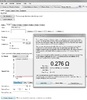
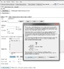
Hi John, Thank you for your detailed answer, However, I fear that you missed my point. I havenât got any concerns about the built current/leakage/polarisation protection on the board as long as designed functions/connections concerned. Neither with charging or USB current per se. I do have serious concerns about some alternative current path that was never intended to exist. In my case, an otherwise open circuit can be closed by flexing the USB socket a bit (via the mail plug) In other word, the USB socket acts like a push button switch or more properly a flex button switch switching power on a specific circuit that unlikely to be powered up this way. The effect is the same as probably all of us experienced with our earphone cords. When one of the wires inside got broken the stereo headphone became mono. Should you have found the right spot and the proper amount of flexing required you could temporarily close the open circuit and get the stereo back. In real life I have experienced the following: 1., Battery attached (both power and charger connectors) fuse blown, USB not attached: The thing is dead.Note: Apparently your logic circuits are hooked to power in behind the fuse which makes sense. 2., Battery attached (both power and charger connectors) fuse blown, USB plugged: She looks OK and even charging happily. Device Monitor: doesnât show any strange things save for the missing cold ohm. Atomizer Analyzer: couldnât find anything, gives a big question mark. Note: Apparently your logic circuit(s) couldn't (or not supposed to) power up atomizer for checking its resistance. 3., Battery attached (both power and charger connectors) fuse blown, USB plugged and slightly flexed: Device Monitor: mostly the same with occasional error message here and there, still no cold ohm Atomizer Analyzer: finding and measuring the atomizer as per normal. Note: It doesn't work with all of my cables but with the one I have used. Some cable just gives error message when flexed. Bottom line: I can switch the power on for the Atomizer Analyzer by simply flexing the USB and closing some circuit that you more likely didnât design to be closed this way. Or at least I hope so, and it is not that you referred as normal to My humble request: I would greatly appreciate if you could have a close look on the Atomizer Analyzer function both hardware and software side (if needed) and explain me which circuit can possibly get closed by flexing my plug.And let me repeat myself: it is not an easy trick. Unfortunately it is my high end default bypass cable that can do the trick, my other cables are apparently weaker than the case/bard/socket combo and a simple error message is the max they can get. But either way, the 3 different readouts above with the corresponding current events are modulated via slightly flexing/ not flexing the USB port. And it shouldn't happen. Thank you in advance

-
When I have experienced this, my battery was connected, however the fuse was blown so B+ actually can be considered unplugged and only B- was present (if at all, dunno) Tonight, I will Check all the possible combinations
-
In that case it is hopefully controllable via firmware, isn't it? Or it is just wishful thinking?
-
I didn't want to abuse the board more but I will do some test when I got home. It is happening for sure when battery disconnected an ballance charging is on. Confirmed for my battery is permanently disconnected by a blown fuse
-
It is not the battery readout. It is the output power. Try to check the atomizer resistance with battery unplugged (both main and charging plugs) When I do it w/o battery I got a big '?' for there is no input battery power that should power up the output circuit. (Battery voltage readout comes from balance charging ports) When I do it with the method described above some miraculous current powers up the output circuit. And this is it. Battery readout, chip readout, charging has nothing to do with it. The only question is the actual output under load.
-
Yep. That is the normal way. But as I have mentioned in the linked post there is a specific position of the USB when it bypasses protection: I have pushed the plug slighly upward accidentaly and this little tension moved something inside powering up the whole board the way it shouldn't have.
-
I got the bad feeling that it is some leakage current from the USB killing the fuses. Details here, but the bottom line is that USB power can directly reach output power circuit. (with or without fuse/battery) And if it reaches without any shut down mechanism a circuit powered simultaneously by full battery input and USB at the same time doesn't sound too promising to me. Sorry, for starting a new topic about it, but my previous one with this finding remained mostly ignored. If I am right, please look into it. If I am wrong, I do apologize for double-topicing. My only excuse is that I want to build a super tight fit triple 18650 mod and the last thing I need to replace the fuse weekly. Not to mention that any external fuse between the board and the batteries wouldn't help either unless I bridge the on-board one first. Edited for clarity: By default, USB behaves as it should.Unintentional power up only happens when some rotating torque is applied on the socketHappened with me accidentally when I have tilted the case w/USB plugged in and it put has some tension on the socket/boardIt is one specific point/position when it happens with a very narrow margin. When I realized what happened found it hard to find the spot again for double-checking.It is a 3D printed plastic case which is probably more flexible than an alloy one.
-
Not completely dead but not alive either. And doesn't work
vapealone replied to vapealone's topic in DNA 200 and 250
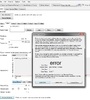
My concern is that the board powered via USB when the fuse is blown (i.e. board powered up w/o surge protection) With good fuse it is OK Besides, as I have added, it does some other thing it probably shouldn't: the current actually found its way to the output circuit. And I think, it could be a problem. Unless there is some shut down hardware option inside, it means that few circuit on the board can get power from both the battery and the USB at the same time which sound like a kaboom to me -
I was thinking a dual mosfet setup: #1 P channel w/ both the gate and the source is on the main (+) #2 N channel in the main(+) / gate#1 circuit with its gate (#2 ) wired to main (-) or last battery (-) In that case, any current coming from a wrong way (regardless of its voltage) trigger #2 closing #1 circuit where Vgate will be V source which is needed for complete shut down if I read it right. Pos: It is an always on thing w/o any consumption unless reverse polarity when it shuts Con: It doesn't necessarily save the batteries. In theory, it should (no closed circuit but the right one) but I have concerns. Any misbehaviour on the board side should do funny things. And I start to think, that some leakage current from the USB killed my fuse. P.S.: Thanks for the thread and thanks Brandon for the info. I was naive As it is stated available in the doc I opened a ticket asking for detailed info for design purpose (dimensions, datasheet, price etc.) That is what I got: HI Gabe You can find all DNA 200 info at http://www.evolvapor.com/dna200.php Thank You, Steve Hope it doesn't mean that we are back to the good old days...


