

alee132
-
Posts
112 -
Joined
-
Last visited
Never
Content Type
Profiles
Forums
Downloads
Posts posted by alee132
-
-
I bought a brand new Fully Max FB900HP-3S from protovapor. I threw it on my RC balance charger and charged it. It charged up to 4.2 a cell perfectly. Whenever I get a new lipo I like to cycle them on the charger a few times before I use it because I can tell if there is an issue with the cell and it also gets them up to full capacity. Well I noticed immediately after the first charge/discharge that one cell only got down to 3.59, the other 2 cells were fine but went a little under 3 probably trying to get the other cell lower. So I tried cycling it again, but it did the same thing. I sent them an message. But this isn't normal behavior that I have seen from my other lipo's before. Am I correct in thinking that there could be an issue with that cell or the wiring too it? I am not going to open it up and check it out as I am hoping if it's bad infact that they will replace it for me as I never even got to use it or anything before I figured this out. Which is why I do it this way to begin with but this is my first fullymax battery. I had a couple turnigy 950 mah nano techs that worked great but I thought I would give this battery a try and this happened lol, its just my luck.
-
Hi I have been building ni200 coils for awhile and now ti grade 1 with the correct cvs file from steam engine. I noticed how ni200 in device manager on the temperature line spikes up and down once it reaches temp. But when I use ti it looks much more like a line once it reaches temp then spikes. Now the ti wire is working great actually but my question is if that is normal behavior or not. I could post pics once i get home if needed. My guess is that it os working correctly because its just not as accurate at temp control so it doesnt show as many peaks up and down at temp.
-
If this is the worst of the issues you would be doing good imo.
-
Wake-N-Vape said:
Hello Everybody! Well, I unfortunately have another Hana V200 failure to report. I received my device yesterday and have had it running for around 20 hours now. While the device screen still functions perfectly (for now), I did discover yet another 510 related problem. The first device I screwed on was a Tugboat V2, and I immediately noticed that the 510 pin in the mod was crooked, and had very tight tension on it. Once I screwed down the atty, the 510 Pin did not spring back up as a normal spring loaded 510 pin should. This is just part one of the problem...
Part 2: Because of the wonky 510 pin, I am also unable to get a consistent vape or consistent ohm readings on my atomizers (with Titanium GR1 & Steam Enginge TFR values - which is all I have tried). I have two DNA 40 devices that both report the correct resistance of the atomizer, but the V200 is consistently lower (around 0.02-0.05 depending on how it feels at any given moment). Because of this, Temp Protection kicks in almost immediately and does not allow me to get a sufficient amount of vapor. My guess is that the positive connection on the atomizer is not making a solid connection to the Hana's 510 pin... So, needless to say... At this point, I have an unusable V200 which will be going back to Hana hopefully sooner rather than later.
I just thought I would share my experience here since I had not read of this specific issue as of yet... And of course, add one more to the list.
I bet its because its getting pushed down against the battery and gets stuck. -
John said:
Partially it will depend on your settings. If you run it at something like 10 watts in battery analyzer, you will get more capacity than if you run it at 200, because some energy will be lost as heat in the battery and wires.
It is a good idea to have the battery somewhat broken in before running battery analyzer.
My most recent tests with the Fullymax have been in the 9.3 neighborhood, at a nice representative 60 watts of output power.
I ran my tests at 50 watts. So I should be running them higher then I guess to get a more accurate reading. Good to know. -
I for sure thought that connector wasn't good enough to handle the amp limit. That's why even though I use the same battery, I changed out the 20gauge wire for 18gauge which may or may not been for sure needed but the connector I changed out for the xt30 connector but with the v200 I don't think there is enough room for doing xt30 so you may have to do bullet connector's or something else. I don't know if doing any of that will void your warranty though.
-
I have already used ni200 claptoned with ni200 and it works just fine on the default curve.
-
Dampmaskin said:
If the resistances differ by a lot, you can get away with using only the lower resistance. Using both will always be more accurate.
You can find a tutorial about it here if you're interested in learning more.
Ok good to know. I will do whats going to be more accurate. I will report my results back here. I am still waiting on my wire to get here for the TI grade 1. -
dsidab81 said:
when setting up this battery under Escripbe > Mod, are you guys using the published 10 or 10.5 Watt hours by fully max or the 8.8 that John mentioned previously?
Would leaving the soft cutoff at 3.09v be appropriate?
Personally I think you need to have 10 cycles of the battery before you should run the battery analyzer and then run it for your wh rating as each battery could be slightly different. Make sure to remove cotton unless you plan on catching it on fire or wasting ejuice. And make sure you fully charge battery then run it, it takes couple hours but will give a good accurate curve. I did it on my 950mah turnigy nano tech and it came in almost exactly as the calculated amount at 10.57 instead of the 10.54. I am waiting on a fullymax 900HP-3s to run in the same mod and if it runs just as good or better I am using it instead because it is slightly smaller and would fit better in my 1590a with more wiggle room. As it is, my 950 turnigy is extremely tight.
-
i would love to go with a 2200mah build but I haven't seen anyway possible unless you want to go with a huge case. But my idea of huge may not be your's or other's view on it. I didn't like how big the 1590b box felt. (I did my first ever mod build in one and ended up taking chip out and putting into 1590g).
-
Dampmaskin said:
For now you will have to go to the coil calculator, select the material and gauge, guess a resistance, and look at the resulting resistance wire length. If too high/low, adjust the resistance accordingly, and check again. Repeat until you're "close enough".
I'm planning a brand new calculator that will make all this a whole lot easier, but it's an ambitious project that will take some time.
Well I noticed that you can pick your wire and you gauge and it gives you a ohm/mm calculation. I used that to figure out the ohms above. So its not automatic but its not too hard either if you do it. I think I got it now I just need to actually try this out on a coil and see if its working like it should. Because I have heard that the wire with the lower resistance is the only one its going to use. If that's true then using both in the tcr calc is going to be off. -
Dampmaskin said:
For the best accuracy, you should enter all wires used. For claptons you can approximate the length of the outer wire by doing the following:
(radius of center wire + diameter of outer wire) * pi * 2 * length of inner wire / diameter of outer wire. (I haven't tested this formula, so double check it before you trust it 100%)
But it if it correct, you can then use the coil calculator to jog the resistance around until you hit the length of each wire. Enter these resistances in the TCR calculator for both coil materials, and you should get a pretty decent temp curve.
Twisted is simpler: Just find the resistance of both wires (again you can use the coil calculator for this, as long as you know the lengths), and enter both resistances in the TCR calc.
OK so if I got 26g ti wire center and 30g ni200 outer. I would do:
diameter of center wire 26g ti = .4mm which /2 = radius of .2mm
Radius of center wire .2mm
Diameter of outer wire 30g ni200 .25mm
Lets say for example a length of inner wire is 100mm
So given these numbers the formula would go:
(.2+.25)*pi*100/.25
(.45)*pi*100/.25
1.413716694115407*100/.25
141.3716694115407/.25
565.4866776461627mm length for outer wire
Length for inner wire 100mm
Now my problem is how do I get the resistances to input from the length?
Also did I even do it the above math right? If so I just need to figure out how to turn it into resistance to input into the TCR calc
I tried to use the following I found from the calc for formula
Ohms/mm
26g ti grade 1 = 0.00365/mm
100 * 0.00365 = 0.365 ohms
30g ni200 = 0.00189/mm
565.4866776461627 30g ni200 * 0.00189 = 1.068769820751248 ohms
100mm of 26g ti grade 1 wire = 0.365 ohms
565.4866776461627mm of 30g ni200 wire is 1.068769820751248 ohms
I think this is correct.
-
I am trying to create a TCR for the dna200 correctly for clapton coils. I am trying to use 26g Ti grade 1 wire as the core and ni200 30g as the outside wrap. I have heard that the coil in the center is what the resistance goes by. Does this mean that I don't need to worry about the wire on the outside for the TCR and just whatever I have as the core? If not, do I just measure the length of wire, figure out the resistance with coil calc and then input both coils into the TCR calc and then use that curve or just use the curve for TI grade 1? Also what about if I want to twist ni200 and ti or any 2 different kinds of wires? Do I need to input both into the calculator or just whatever one is going to be the lower of the 2 resistance wise?
-
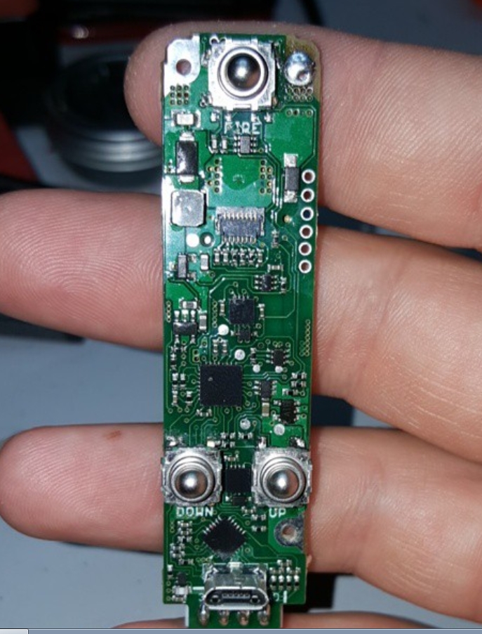
I also don't get why hana bothered with putting anything on their buttons if they were able to spin. It's the one main reason I wouldn't buy this. I am also waiting on evolv to make the reference case or someone to use it and make it available for bigger battery's. They did this on shapeways and it's great but I want mine to be made of aluminum or some other great metal. Anyways I hate to see all these issues because of hana rushing things and not doing things the right way. As a modder I could tell that was something that had to be addressed just by looking at it within 10 seconds.
-
Wow, I have been using and loving this board so much but I had mamu's screen holder so it made it easy to tuck it under and avoid the fire button but I could tell it could be an issue if you don't do something to avoid it. It's sad to see hana was messing up and properly securing the screen to were the cable wasn't getting in the switches way with double sided foam tape or something else. I don't get it. But hey I am glad they caught the issue before they kept pumping out mods with the problem. These kinds of things are not the fault of the chip but of the mod maker imo and I hope people understand that.
-
xevape said:
[QUOTE=Brandon]The audible clicks would drive me nuts.
The clicks makes me feel more manly. I also took apart the original buttons and retrofitted the tact buttons to make them non audible clicks but that's a whole nother' story.[/QUOTE]
Ya it looks like you kinda took the bottom of the original button and put the top of the KSJ buttons on. -
xevape said:
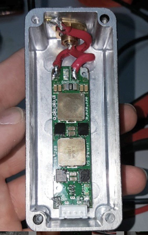
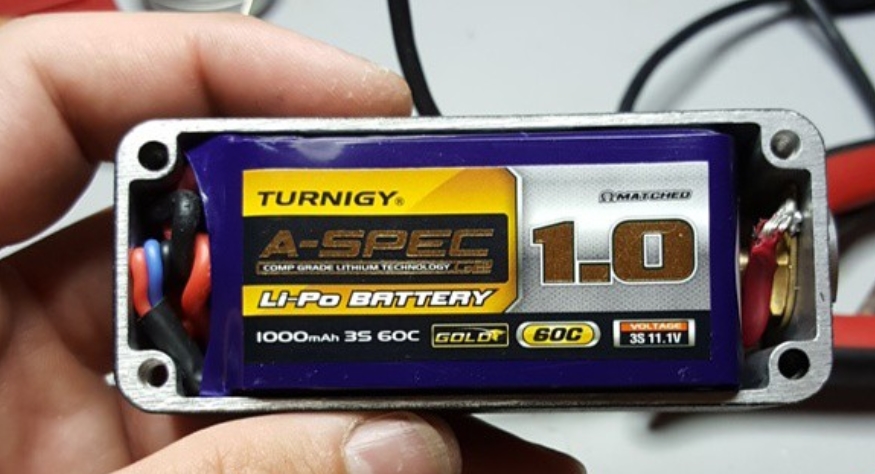
Nice job on the switches! great job on fitting all that into a 1590a. I had to do some work to even make a 950mah fit. It doesn't look like the battery will fit with the lid on at all and if it does will it have any wiggle room for swelling at all? -
Wick said:
Shapeways DNA200 Reference Case printed in blk. Just playing with plastic!!
Just curious if you put a clear coat or anything on that print. Just from personal experience in the past I had my first shapeways printed mod in the dyed variety and I didn't put any coating on it. Eventually it started to show and I now put a matte clear coat on all my prints before assembly and they seem to hold up better for longer. -
Very impressed with you guys going ahead and doing this since some in the community wanted the option of not having to use lipo's. Sure they don't get the full 200 watts but they get more than enough imo and it gives them all the wonderful features of the dna200 and escribe!
-
Wow 1000mah in 1590? That's damn good. I barely could fit a 950 and that was with a faceplate and I had to remove somethings to make it work. Wonder what battery you will use. Very interesting.
-
Dejay said:
Oh this is awesome! I was wondering the other day if this was possible! This removes one of my main downsides for the DNA200 for people who like externally charged batteries. Thanks evolv!
I wonder how if you have taps running to them will you be externally charging them? Or can you just have taps running to the correct places on a battery tray instead of directly to battery's? That would be epic. Infact I don't see why not. This will make some of the people that were complaining about not being able to use 2 18650's happy. But I don't really see the point for 2s lipos now that I have looked at them vs 3s lipo's. So mainly this only makes sense for 18650's or 26650's imo. -
scoopy said:
Ipv3 li with samsung 25rs....it goes up to 200 but not true 200 lol
Oh ya and how long of vape time do you get on the 2 18650's at that kinda wattage? -
I would have to agree that if you vape that high of wattage normally you are going to for sure need more than the 900mah battery. For sure go for the 2200mah battery. Besides the mod shouldn't be too much different in size to your ipv3 li. The 900mah mod on the otherhand can be made much smaller but it's not going to get much vape time at that kind of wattage. BTW what case on shapeways takes a 2200 turnigy? Just curious about the size of it and form factor, shape, etc. If it's not too huge I might be interested myself. But ya, don't bother with the 900mah one as I can't see you getting more than an hour maybe 2 depending on how often you take a pull with that kinda wattage.
-
So basically by shorting it in that way you are trying to get a internal resistance reading? I am wondering if this is what this setting is for and is this the best way to figure it out. I just want my mod to be tuned perfectly if possible. Not saying anything is off at all but if there is a way to easily read and adjust for any internal resistance than I am all for it. But I figured maybe I was missing something here as my setting doesn't change on its own I either assume it's not changed any way but manually or my mod was not off enough to need adjustment. If it's changed manually how would one best read for it.
Brand new Fully Max FB900HP-3S not discharging balanced
in Batteries and Charging
Posted
I agree, it sounds bad too me but I wanted to make sure I wasn't incorrect. Well I am just waiting to hear back from protovapor about it, messaged them last night and it's still early but no response thus far. I would assume they would replace it as it's brand new. Of coarse I had to solder a connector to it in order to plug it in and charge it and check it out.