

Tubbyengineer
-
Posts
10 -
Joined
-
Last visited
Tubbyengineer's Achievements
Member (2/3)
2
Reputation
-
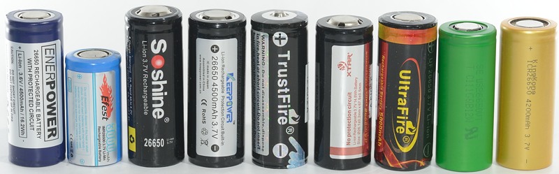
Yep very good - that ones the right size, now have a look at this pic - with several "26650" cells side by side (You can ignore the one 26500)
-
It's more to do with the fact that there are cells out there that are over the 65mm length - if you design something to take a cell of 65mm length then it takes 65mm length. If a company then markets a cell as 65mm long (ie - a 26650 cell) but it's actual physical dimension is 67.2mm then who is wrong? the company who makes the device or the company who makes a cell that doesnt even conform to the size it's marketed as? Giving some extra space is fine, and has been accomodated in the design, but if a cell is so far out of spec then you'll get problems - whether it's the cap not sitting flush due to the extra length, or damage caused because someone tried to force the cap to sit flush when using an extra long cell.
-
I'm really only seeing one issue here - User error. If you tighten the battery cap more than finger tight then you stand a chance of damaging either the Mod or the Cell, either will cause serious damage and may well result in venting. If your cell is too long and the battery cap doesn't sit flush once it's finger tight then DON'T force it any tighter you'll crush the positive contact or the battery cap and risk a short. The modified part is simply an insulator that will spread the load across the whole of the positive terminal cap making it much harder to damage by overtightening. I other word's they've had to "brute proof" the mod to ensure that people cannot use brute force to damage the positive terminal of the mod or cell. It really is user error - overtightening things usually results in them breaking, why not try it with some of your other favourite products - I bet they'll break too...
-
Therion DNA 250 Ignition Without Atomizer Problem
Tubbyengineer replied to elvinyilmaz's topic in DNA 200 and 250
You need to put on a known NON TC atomiser and run the atomiser analyser - it appears you are getting a short on the 510 - either from the atomiser - or more likely from a faulty or dirty 510 on the mod. Run the atomiser analyser with the known NON TC atomiser, and then without an atomiser - You should get just a ? without an atomiser, and close to the known reading for the NON TC coil, If you get anything other than the ? with no atomiser then the fault is within the mod and is a short either in the 510 or the wiring leading to the 510. -
EScribe Suite 2.0 (for DNA 75 Color)
Tubbyengineer replied to James's topic in EScribe, Software and Firmware
I've been having a poke and noticed that using Escribe 2 with a DNA75 the indicator light settings are not loading correctly when you load a theme. I have a theme setup with Indicator light settings fading in and out for all 4 actions and have just redone the light settings and saved them using the Theme designer. Whether I connect the mod and Download theme from device or load the profile from disk going to indicator light just gives me three solid lights - the fades I'd setup are missing. Not sure if this is an actual bug or just default settings for the light but it would be nice to have the indicator light settings I'd programmed available rather than having to redo them... -
Incorrect sizing of battery analyser graph
Tubbyengineer replied to Tubbyengineer's topic in EScribe, Software and Firmware
Thanks for that, it has indeed fixed the scaling problem... -
Incorrect sizing of battery analyser graph
Tubbyengineer replied to Tubbyengineer's topic in EScribe, Software and Firmware
Hi so I've just bought some new batteries and I'm running the battery analyser, the graph seems to have shrunk up into the top left corner of the screen and approx 1/4 normal size. Has anyone else had this problem? Is it a bug or is there something wrong on my end. Escribe is Version 1.2 SP3 Windows 8.1 (Cause I hate 10)... -
Ah, Ok - I figured it out by accident when I changed my monitor settings a moment ago. There are two halves to the colour box, so use the plus sign to create a box for a new LED event then click in the box to set the base colour - so for fade in you start with black so when the colour swatch panel comes up select black then ok it to fill the box black, then click in the right hand half of the black box and select the colour you want to fade in to - lets say yellow, then Ok it. You should now see the box filled with a graduated black to yellow. To fade out you do the same as above but switch the colours around so start yellow then pick black - this should give you a box graduated yellow to black. The full fade in / out sequence require two boxes - one from black to yellow and one from yellow to black. The final step is to click the little arrow on the first box, this will make it yellow and set the device to keep looping the led back to that point after completing the sequence of boxes - So in theory you could do a complicated sequence and have it infinitely repeat or do thre or four colours ending with the device looping around the last two boxes - or wherever you place that yellow arrow...
- 1 reply
-
- 1
-

-
Does anyone know how to acheive the fading effect on the DNA75 fire button? I have a Therion BF that fades Red on and off whilst charging and would like to use this effect on other devices I own. I cant seem to figure out how to do it - I've managed to get an occasional random fade on but never of the right colour - I've only managed to achieve that twice in white to black - and even that was by chance...
