

fostac
-
Posts
10 -
Joined
-
Last visited
Never
fostac's Achievements
Member (2/3)
0
Reputation
-
Trouble controlling firing switch with MOSFET
fostac replied to fostac's topic in Connectors, Components, and Accessories
If I understand how the fire button works correctly, you can use an NPN transistor (2N3904 is fine). With base at or below emitter potential (less than voltage drop of base-emitter junction), unbiased, no current flow. Base forward biased (3.3V is plenty), current flow. Fire terminals would be +12 side to collector as shown and the other side replaces where ground is shown to the emitter resistor. CPU output pin to base resistor (your CPU output pin is simulated by the 0 and 3.3V sources in the screen grabs). Hopefully the simulation makes sense to you. Forward bias current through base of transistor (base emitter junction) and it conducts. Zero bias current, it doesn't conduct. Classic emitter follower. You may have to experiment with what the DNA wants to see at the other side of the fire button. Another approach would be classic open collector / common emitter configuration. See the third simulation screen grab. Some CPUs have at least a few open collector outputs. If yours does, you don't even need a transistor, just a current limiting resistor. [/QUOTE] This worked perfectly! I got caught up over thinking it after reading that other thread where he settled on using a relay. Thanks again Mad Scientist [/QUOTE] Awesome, great news! Can you post the schematic of what you settled on? I'm curious as to whether the emitter follower configuration allows enough current to flow to fire the DNA 200. Or did you go with common emitter? Something else entirely?[/QUOTE] I ended up with a common collector configuration that seems to work well. I can trigger a single fire by pulling HIGH for > 10ms.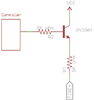
-
Trouble controlling firing switch with MOSFET
fostac replied to fostac's topic in Connectors, Components, and Accessories
If I understand how the fire button works correctly, you can use an NPN transistor (2N3904 is fine). With base at or below emitter potential (less than voltage drop of base-emitter junction), unbiased, no current flow. Base forward biased (3.3V is plenty), current flow. Fire terminals would be +12 side to collector as shown and the other side replaces where ground is shown to the emitter resistor. CPU output pin to base resistor (your CPU output pin is simulated by the 0 and 3.3V sources in the screen grabs). Hopefully the simulation makes sense to you. Forward bias current through base of transistor (base emitter junction) and it conducts. Zero bias current, it doesn't conduct. Classic emitter follower. You may have to experiment with what the DNA wants to see at the other side of the fire button. Another approach would be classic open collector / common emitter configuration. See the third simulation screen grab. Some CPUs have at least a few open collector outputs. If yours does, you don't even need a transistor, just a current limiting resistor. [/QUOTE] This worked perfectly! I got caught up over thinking it after reading that other thread where he settled on using a relay. Thanks again Mad Scientist -
Trouble controlling firing switch with MOSFET
fostac replied to fostac's topic in Connectors, Components, and Accessories
Still having trouble reliably triggering the fire action. I'm using a 2N3906 PNP transistor driven by a ~3.3v signal. I either burn out the transistor or I'm unable to close the switch so it just continuously fires. I've tried pulling a 2N3904 NPN, different arrangements of pull-down or pull-up resistors and I'm still lost. A couple things I've learned though: There is a 1k resistance between ground and the Fire - header. My multimeter is telling me 0.5ma is running across the headers, but that's way too low, so I'm not sure what the actual value is. Any help or clarification on John's solution from this thread would be amazing. -
Trouble controlling firing switch with MOSFET
fostac replied to fostac's topic in Connectors, Components, and Accessories
I wasn't sure what kind of current to expect from the switch? I had trouble burning out a 2N3906 I tested it with, so I didn't expect the current to be very low. I'll measure it tonight to know for sure -
Trouble controlling firing switch with MOSFET
fostac replied to fostac's topic in Connectors, Components, and Accessories
I'm interested in adding functionality to the board via an external microcontroller. I plan on adding additional sensors for control/interface. -
Trouble controlling firing switch with MOSFET
fostac replied to fostac's topic in Connectors, Components, and Accessories
Hi, So I'd like to control the firing switch via a microcontroller, but I'm having some trouble. I understand that unlike the up and down switch headers, the firing header is at battery voltage and is active high. My question is how do I switch that ~12v with a 3.3v signal from the microcontroller? Will I need two separate transistors, one PNP mosfet for shorting the switch and another for controlling that mosfet? Should I step-up the 3.3v? Any help would be greatly appreciated. -
Source of between +3.3 or +5V on the board?
fostac replied to Mad Scientist's topic in Installation and Assembly
Exactly what I was looking for, thanks! -
So I'm making a mod that needs to be able to prevent the DNA 200 from firing via an external microcontroller. My first thought is to tap into the six pin button breakout header on the left of the board and drive the buttons via the microcontroller similar to this. However, I believe I'll run into problems with the board unintentionally firing when entering locked-mode, stealth-mode, etc. even when the safety is supposed to be on. I'm looking for a way for the safety to only restrict firing of the coil without interfering with mode-switching or other commands. So then my thought is to interrupt the connection to the coil with something like a mosfet. That way I get the 'Check Atomizer' error when the board tries to fire unless the microcontroller controlling the mosfet lets current through. This is the method I want to use, but I can't there is a mosfet or relay small enough to fit in the case and be controlled by the microcontroller that also could handle the crazy output current. If you have any suggestions or if I'm missing something on the board, then I could really use some help Thanks!
-
Source of between +3.3 or +5V on the board?
fostac replied to Mad Scientist's topic in Installation and Assembly
Did you ever figure this out? You're correct that picking up from a cell on the balancing connector would unbalance the battery unless you juggled all 3 cells. It doesn't make sense for me to put a regulator on the board I'm trying to power if there is already a regulator onboard the DNA 200 for the IC. I'm waiting on a fuse for my board so I can't probe around, but this thread mentions a jumper and then power for an LED fire button. This or something similar might work?
