

student_moses
-
Posts
5 -
Joined
-
Last visited
Never
student_moses's Achievements
Member (2/3)
0
Reputation
-
Well, it looks like a USB interface may be a viable option after all! I just found this host USB shield with dimensions of 25mm x 19mm, and it appears to have an option for built-in CDC protocol software. I might try to make that work as well.
-
As John said, the Arduino Nano doesn't have host USB, so I would have to use a host USB shield. If I find a 5V one that could reasonably fit in a box mod, sending commands over USB would be a viable option. Rather than use a MOSFET for the fire pins, I think I'll just opt for a small signal relay. There are some extremely compact ones available (this one, for instance), and the dimensions of any MOSFET circuit I made would likely end up being larger than the 19.3mm x 7.6mm x 5mm package specified for that model anyways. I'll just have to position it away from the magnetic latches.
-
Thanks for the reply John. If I used a P-channel MOSFET in place of an N-channel one, and a level shifter to bring the output voltage of the Arduino above the battery voltage, wouldn't that just cause the MOSFET to turn off when voltage is applied? I'm not sure I follow. I'm also not sure why the fire pins being active high changes anything. Aren't the up and down pins active high as well?
-
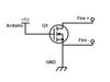
Here's a diagram of what I'm talking about: Q1 could be any logic level (threshold voltage < 5V) MOSFET. S1 is just a momentary switch for manual operation.

-
Hello, I was planning on building my DNA 200 box mod with an onboard Arduino Nano to handle addressable RGB LED lighting, tilt/accelerometer inputs, and capacitive touch inputs (mainly to sense when the user's lips are touching the drip tip). In order for capacitive and tilt sensing to work properly, I need a way of using the 5v PWM pins on the Arduino Nano to register simulated button presses on the DNA 200. This is where a logic level transistor might come in. My plan was to connect the drain and source of a transistor to the Fire+ and Fire- pins respectively, and then connect a PWM pin to the transistor's gate and connect the source to the DNA's ground. This would be repeated for the Up and Down pins on the DNA 200. In theory, that would allow me to use the Arduino Nano to fire and adjust settings on the DNA 200, as the transistors should behave as switches. However, because I don't know how the inputs are designed, I can't say for sure. I've been operating under the assumption that the Up/Down + pins are just Vouts at the logic voltage of the board, and the - pins are sensing for voltage (indicating a closed circuit). I was hoping that someone here could tell me if my assumptions about the operation of the DNA 200 are correct, and more importantly, if my idea of using transistors as remote buttons would work. I could just test it when my DNA 200 arrives, but I'd rather not fry it if I'm wrong. Edit: fixed a mistake in my description of the wiring.