NickIcon
-
Posts
4 -
Joined
-
Last visited
Never
Content Type
Profiles
Forums
Downloads
Everything posted by NickIcon
-
That does look much easier than digging up the tracks in the PCB, although I may have to wait until my DNA200 actually arrives to get an idea of whether it'll be feasible - still looks very small! I was planning to omit the "ID" pin - I didn't think it would be required but a second opinion would be appreciated.[/QUOTE] You have to remove the USB socket to get to where he put the arrows.[/QUOTE] Oops - yes, I see it now. I'm starting to think I may have to leave this until the mod after this!
-
It has just been suggested to me that copper contacts may get gunked up quite quickly with any arcing - magnets sound like a great idea!
-
That does look much easier than digging up the tracks in the PCB, although I may have to wait until my DNA200 actually arrives to get an idea of whether it'll be feasible - still looks very small! I was planning to omit the "ID" pin - I didn't think it would be required but a second opinion would be appreciated.
-
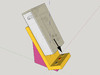
I'm in the process of designing a custom DNA 200 box mod and am thinking of making a charging stand for it as well. Originally I had been thinking of using an inductive charging module a-la VaporShark rDNA40. Given that I would be making something on the bottom to align the mod on the stand anyway it seemed like a better idea to turn those into the contacts rather than bundling in the extra wireless charging components. Here's the concept so far: The mod has matching female contacts on the bottom: two grounds on the outside and live in the centre so that the mod can be put down on the stand either way around. The priority is to make the connection easy to make so I've dropped the idea of moving the mod-side USB port to the bottom: I don't want the mod to "stick" to the stand when it is removed and I want to avoid having to align the USB connectors (and then push down) when it is placed on the stand. Of course this means that the stand will serve to charge only and that the USB port will still be required to connect to a computer to use Escribe but where day to day use is concerned I'm more than willing to make that sacrifice. On that note however, I'm sure that the on board USB connector could be removed and all contacts re-routed to a custom connector with all 4 USB contacts but I'm reluctant to make any changes to the board itself. My intuition says this shouldn't be too difficult - find the positive and ground that the USB connector connects to on the board and solder on the leads to a connector on the mod that fits to the stand. On the other hand my understanding of electronics is limited... Other than not having the mod connected via the USB port and the to the charging stand at the same time, can anyone enlighten me as to whether this would work or not? The follow-up question is where to solder on my leads to the mod's stand connector - without compromising the existing USB port. Any help would be much appreciated!