Focus
-
Posts
8 -
Joined
-
Last visited
Never
Focus's Achievements
Member (2/3)
0
Reputation
-
Help me understand this a little more. I shouldn't need a chassis ground if I have run a separate wired ground?
-
I understand now what you are saying. I may be lucky and not have to face that issue because I have installed that acrylic ring under the 510 so I hope it will help isolate from the aluminum.
-
I am only using the 18guage from the board to the 510 which is about 1.5" length. According to specs 18 guage is good for 30A @ 12VDC with a maximum length of 3 feet which will give a maximum voltage loss of 3%. So at 1.5" I believe it's minimal. As for the solder I did the same thing tinned the wire dropped some solder into the hole and then heated it all up ! As for the hotglue, I only used it for the LED board everything else is epoxied with thermal conductive epoxy. And the wire I use for that is 24AWG, who needs more for 20 microamps.
-
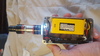
I ended up using 18 Guage stranded wire since I didn't have any 16 guage on hand. Anything bigger would not fit through the hole on the bottom of the 510
-
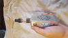
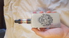
I drilled a 3mm hole ( the size of the LED ) in the casing next to the 510. I measured the 510 for the dimensions of the acrylic ring, fit it on so I can mark the hole for the led on the acrylic ring ( you need the led to stick a little in to the ring to illuminate ) I then hot glued it all to the underside in case I needed to replace the LED or other part.
-
I actually used an L4931 3.3V regulator in a to-92 package. Here is the datasheet: http://www.adafruit.com/images/product-files/2166/2166datasheet.pdf Wiring was simple. It has Voltage IN, Voltage Out, and Ground, I wired the resistor in series on the output to limit current. So it goes like this: Output of my external firing switch goes back to the evolv and to the LED board, ground is tapped at the evolv board and output from regulator to the led. The other side of the led goes to a resistor and then ground.
-
Chris, what I did was this: Seing as the Button has battery voltage, I took the output of my externakl switch and ran it back to the evolv board and my led board, dropped in a 3.3V voltage regulator and 15 OHM resistor, that way no matter what the battery voltage, the LED always gets it's 3.3V
-
So here it is guys (and girls). My first attempt at building a MOD. Parts: Evolv DNA200 Board and screen ZIPPY Compact 1300mAh 3s 40c Lipo Pack Modsledz DNA200 Board Holder V1 VT-B510 Varitube 510 Connector PS-MSW1201-Mitec 12mm Momentary Push Button Switch Flat Top SparkFun Max Power IR LED Kit - Converted to run a LED Instead on an acrylic ring.