

Flavored
-
Posts
6 -
Joined
-
Last visited
Content Type
Profiles
Forums
Downloads
Everything posted by Flavored
-
And, notta chance I'm gonna poke that with a hot metal stick with a glob of conductive material on the end with a power source connected. And if I'm gonna carefully disconnect said power source, I think I'll just ask for RMA. Thanks for the help!
-
I think that is a reflection, but I'll check. All soldering was done on the other side.
-
Amazing what a magnifier on an iPhone can do, that strand didn't show to my naked eye. I'll examine that board more closely with a real magnifying glass tomorrow, then see if I think I can get my fine point tip on it with a little drip of solder. Thanks for the input!
-
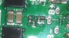
These microscopic things on the right? Or these microscopic things on the left? Or these microscopic things on the back of the USB (and above)? If I had to guess, that one on top of the first pic doesn't appear to be properly attached.
-
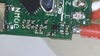
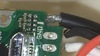
Exact same issue on one I wired up this evening. Cell 1 at 1.85 V, Cells 2 and 3 at 3.7. I soldered the balance wires directly to the board, no room for the connector in that BRD squonker. After I had it all done, hooked it up to Escribe and upgraded firmware, then looked at the monitor. Battery pack indicating 9.3 volts. So I unplugged it and took it back to the soldering station and hit each spot with the iron again holding the wire down with one of the tools. Hooked it back up, still the same. One more try adding a spot of solder to the #1 spot on the back side, no change. Oh, and I metered it in between the solder jobs and have a nice 3.7V on all three cells and 11.1 for the pack each time, front and back (ie - the pads, not the wires from the battery). Think there's an issue with the metering on the board, seeking guidance.
-
Presuming I have a supply capable of feeding it, is the charging capability of the board 1A at 11-12 volts or something different?


