

eagleswind2
-
Posts
18 -
Joined
-
Last visited
Never
Content Type
Profiles
Forums
Downloads
Posts posted by eagleswind2
-
-
I have a DNA 40 chip that has solder going from one connection to another. How do I clean off the old solder in between the two connections? Nothing I've tried seems to work.
-
Thanks for everyone's input.. I'll get the knack of this yet. lol..
-
What can you suggest for adhering the chip to the screen. For now that's my only option. Thanks again
-
Thanks Dave I appreciate your response. I've done pretty much all of what you're saying except for the poss and neg leads. I cut them to length then solder and place the battery tray in place. Building the boxes is my expertise but the electronic portion is a bit of a challenge yet. Im no stranger to soldering but I am on such a small scaled item as these chips. Why the lED came off the ribbon I don't understand but evolve will repair or replace the screen for me for a minimal fee. My issue now is securing the screen and the chip to the wood boxes I make. I've been told double sided tape heat range 200deg. +, silicone, glues etc. I wanted to get the 3d chip cradles and such but they wont fit in my boxes due to limited space. Im now looking for the best adhesive to use, and where to purchase it. Thanks again
-
tyvm for your help. Much appreciated.
-
Just my luck then for its a small screen and being nearly 60 yrs old my eyes aren't like they should be. LOL.. maybe Evolv will repair for me for a fee. Thanks guys
-
Finally found the issue and everything worked great so went to do the final install and the darn LCD screen broke loose of the cable..
-
While installing a DNA 40 into my box the lED screen broke loose of the cable. OH OH.. would it be repairable or is it toast now?
-
thanks awsum140 but while soldering I leave the battery out. Once I get one wire soldered then I'll install it and make sure the board itself is working properly and do the same for each wire soldered. That way if something acts up Id know which wire it giving the problem. After all the wires are in place it all seems to work great but I find that later in time when I go to continue to hook up the switches i'll test it one more time and POOF, there it goes again for no apparent reason...
-
I also noticed on occasions the screen would read "Atty locked press up and down" I would press the power up and down at the same time but nothing would happen..
-
This is the first box I've built from start to finish but having issues with the DNA 40 chip. I get the wires soldered on the chip and everything seems to work fine when I use the onboard buttons. All of a sudden the screen flickers and the power down mode seems to kick in with no off board switches connected yet. So I take the wires back off in fear of maybe a strand of wire is crossed to another terminal. I've done this 3 times now and seems to get better each time. The 4 time I rewired it I was able to start connecting the 510 connector and continued to the fire switch, the power up switch while checking the chip after each connection. When I got to the final switch (power down) it suddenly started to do the same thing. I disconnect both power switches hooked up the battery and turn it on and each time now it powers down to 0 without doing anything. Does anyone have an idea of why this is happening and what would be the cure? I hate to take all the wires back off again and start all over if I don't have to. Just about at my whit's ends here. I don't see any solder or wire strands crossing over any where.. Heeeeeelp!! lol
-
 1
1
-
-
I noticed while trying to solder the recommended wire to the dna 40 chip the 24 awg wire fit well in the contact holes in the chip but the recommended 18 awg wire would not without fraying. I've tried both the solid stranded wire and also purchased the silicone wire which neither could be twisted enough to fit through the holes. So do you drill the holes larger or lay the wire on top the holes in the chip and solder over them? If the wires don't fit what purpose do they serve? Thanks
-
Thanks for your help. Much appreciated
-
Im getting ready to wire up my first DNA 40 chip. Before I do does it matter which 2 prongs out of the 4 I use on the C&K tactile switch for the power up and down? Also does it matter which one is used for the positive side and the negative side?
-
Thanks for the advise. I want to do what it take to make the inside as nice as the outside. One we purchase awhile back ago the electronics was stuffed with paper towels and silicone. Scary thought
-
Thank you. Are there guides available or need to prefab them as well?
-
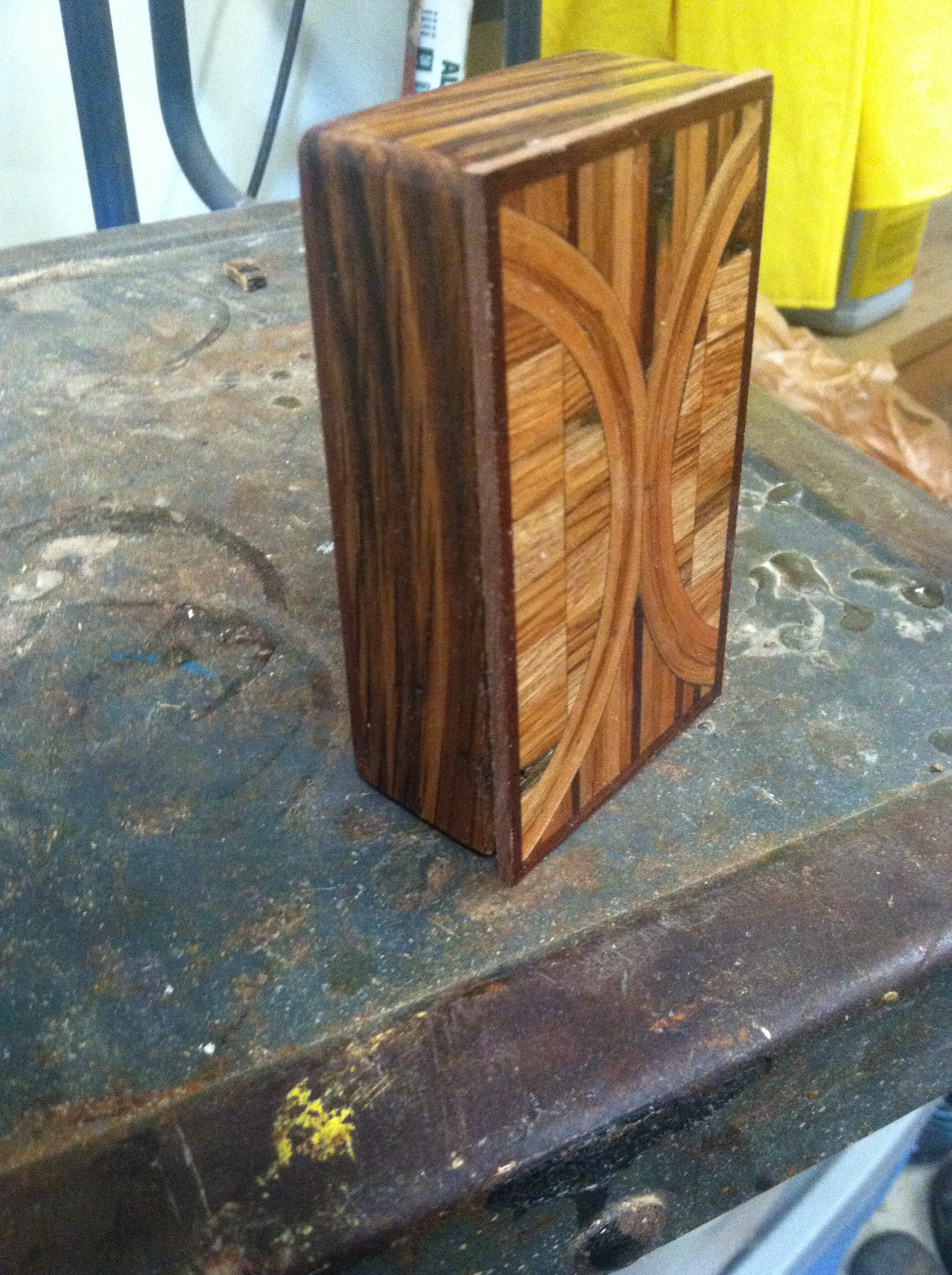 I'm completely new to building mod boxes and it's electronics but not new to custom wood working. So I'm here seeking help, suggestions and ideas. In my boxes I'm using the DNA 40 chips and the next will be the DNA 200 chips. My major question is now how do I secure the LED screen to the wood box itself? I assume it would have to be easily removable in case of repair or replacement. Some of my boxes are Hammond size which has space to work in while the others are mini size with limited space. I'm also looking for a good source of supply for quality parts used in the boxes. Im using Evolv for the chips, Mitec 12mm fire button. V4 510 connector, C&K tactile switches for the power buttons and 18 and 24 awg silicone wire. All my boxes are made from 100 yr old barn wood so I call them my resurrection mods for bringing the dead back to life again.
 ") . So if anyone can help with advise, ideas and such it would be greatly appreciated. Here are a couple of 20 boxes which are the Hammond size.
. So if anyone can help with advise, ideas and such it would be greatly appreciated. Here are a couple of 20 boxes which are the Hammond size. 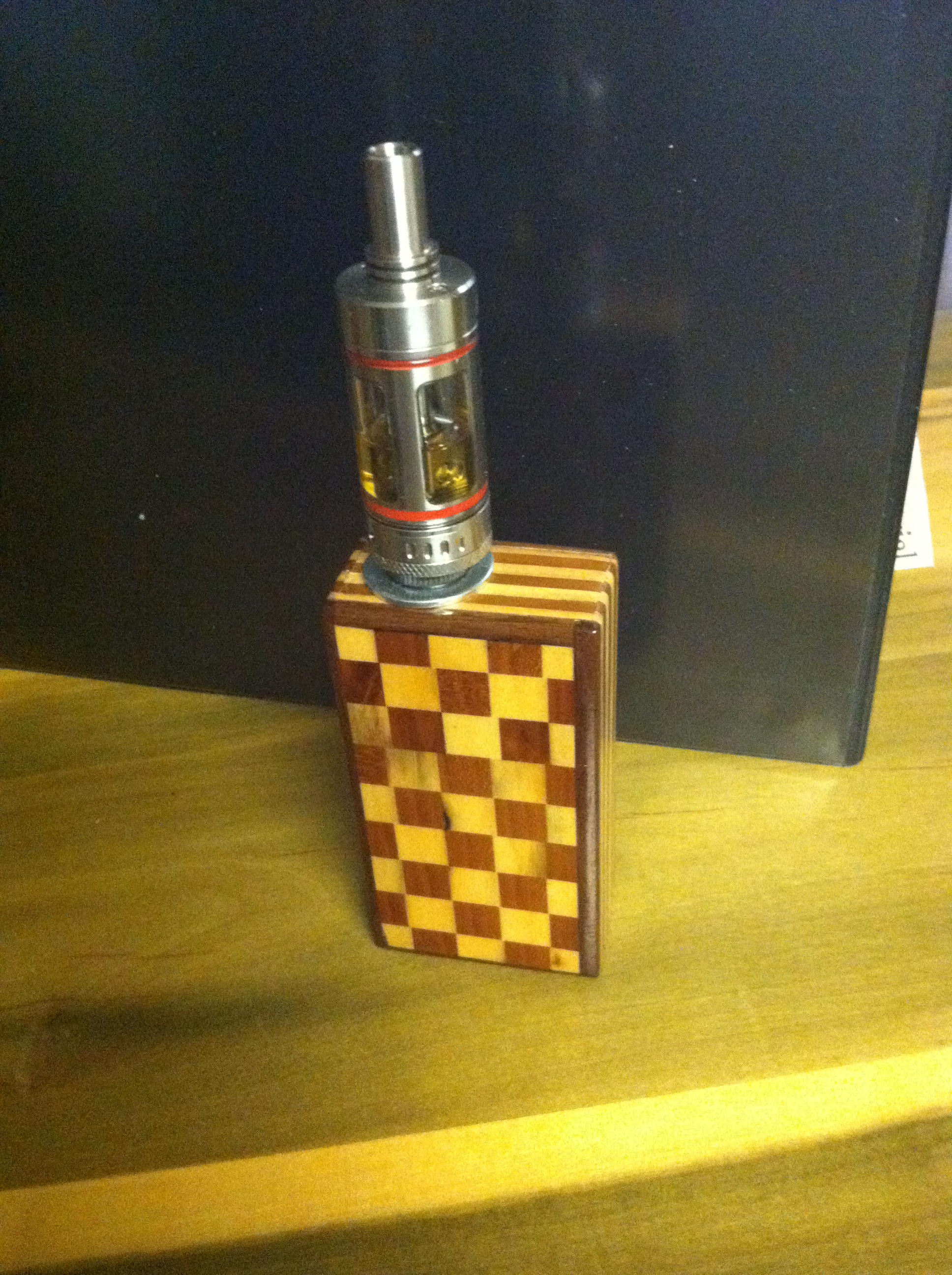
 I'm completely new to building mod boxes and it's electronics but not new to custom wood working. So I'm here seeking help, suggestions and ideas. In my boxes I'm using the DNA 40 chips and the next will be the DNA 200 chips. My major question is now how do I secure the LED screen to the wood box itself? I assume it would have to be easily removable in case of repair or replacement. Some of my boxes are Hammond size which has space to work in while the others are mini size with limited space. I'm also looking for a good source of supply for quality parts used in the boxes. Im using Evolv for the chips, Mitec 12mm fire button. V4 510 connector, C&K tactile switches for the power buttons and 18 and 24 awg silicone wire. All my boxes are made from 100 yr old barn wood so I call them my resurrection mods for bringing the dead back to life again.
Cleaning solder
in General Discussion
Posted
A solder sucker didn't work and I have to order the de-soldering wick so I haven't tried that yet. It is both the battery pos and neg terminals touching the usb charging terminals.