

igipit
-
Posts
5 -
Joined
-
Last visited
Never
Content Type
Profiles
Forums
Downloads
Posts posted by igipit
-
-
Hello people.
Doing some experiments (battery discharge curvers) I damaged my DNA200 configures with 2s LiIon .
Now the board displays the "CHECK BATTERY" and the battery is shown totally empty (batteries are OK). Connecting the board via USB to escribe , cell #1 is recognised but cell #2 has zero voltage, while #3 (not installed) shows a value floating around 1.58V.
The battery pack shows about 5.5 V.
I presume that the battery management chip, the Texas Instruments BQ76925 placed near the USB port, is damaged because it provides the cell voltage measurement analog front end to the SAM D21 ADC. Following the pcb traces I made sure that cell voltages arrive at the BQ76925 pins.
The BQ76925 is a 2$ chip, so that i've no problem to try the substitution because it is a SMD with exposed pins suitable for manual soldering.
But here is the problem: the Texas Instrument BQ76925 does not officially exist with exposed pins. The TI catalog contains two version of the chip a TSSOP-20 and a VQFN-24 but not a Quad with 4x6 exposed pins.
Thus, my questions are
1) Can you solve the mistery of the existing non existing BQ76925 ?
2) any suggestion to work around?
Thank you.
-
May be you misunderstood me, it is exactly what i'm saying : the whole static resistance must be known to precisely estimate the temperature variation.
I have argued on the fact that the 510 connector resistance (that measured by means of the copper tool) is only a fraction of the whole static resistance. Which is the utility to know only the 510 resistance? -
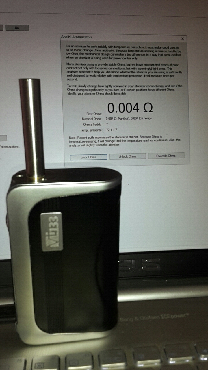
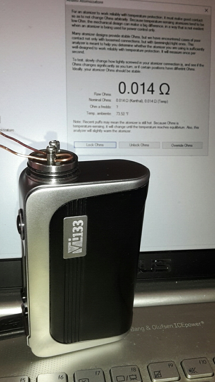
Look at the two pictures. In the first one I measure the resistance of the soldered cartomizer and i get 4 mOhms. In the second picture i measure the resistance of a UD RDA deck with the two pins short circuited by a 1 mm thick copper wire and get 14 mOhm. Note that both the RDA deck pins and the RDA 510 connector were carefully cleaned before I placed it on the VT133.


I think that the entire contact chain resistance should be accounted for as the device resistance and not merely that of the 510 cnnector. -
could someone tell me what am I missing?
Using the copper calibration tool does not reproduce actual vaping conditions. An atomizer 510 connector is not a full copper contact, it has a copper (or brass) central pin and an SS screw. Furthermore the static resistance of an atomizer is not determined by the 510 contact only but by the entire chain of contacts from the 510 to the resistance wire contacts.
If I measure one coil resistance with a precision milli-ohmmeter i get 329 mOhm, but if I place that coil into the KFL deck and screw it into my Vt233, it reads 355 mOhm: 26 mOhm difference! But if I screw in a soldered cartomizer, than I get 4-5 mOhm, likely the same value I would get with the copper calibration tool.
DNA200- battery magement failure
in Connectors, Components, and Accessories
Posted
@VapingBad & @Chunkybutt200: thank you for the advices, I agree with you.
@Chunkybutt200: you are right if the "DNA200 BQ76925" version has an exposed pad, bud I never saw a 4x6 Quad chip with exposed pad.