
scooby
-
Posts
44 -
Joined
-
Last visited
Content Type
Profiles
Forums
Downloads
Posts posted by scooby
-
-
BillW50 said:
Sorry... This piece of advice just popped in my head and it just keeps repeating like a song stuck in your head. Yes I heard it before.
If it doesn't fit, use a bigger hammer. If it breaks, it needed replacing anyway.
Ha, and if it's new, needs a hammer and still breaks it needs a redesign.
The mod I was using it in uses magnets for the cover. Just as I got the clip positioned ready for the hammer it showed a real affinity to the magnet and I'd hit my thumb.
Thing is, imo in this case (or should that be enclosure) a circlip is superior to a 'C' clip -
VapingBad said:
I didn't realises you were a fellow Brit, yeah the SV is probably the best option over here. I have a couple and they seem good, not had a chance to put one in a mod yet though.
I agree with VB, now StealthVape have an alternative I'll be getting one with my next order.
The laughable shipping from protovapor was a factor in my giving the Cisco a try. -
Wayneo said:
Either I have misunderstood the modcrate writeup or it's not been updated with newer information.
At first I also thought it was only 18mm diameter, not 22mm, but the 22mm is in the details. Odd naming for the non builder(me), but clear to you guys.
Ah, Modcrate also make a 510 with a wave spring and circlip, but it's not the Evolv 510. It has an unusually large 18mm x 0.75mm thread.
That could mean that the wave spring is also a larger dia and have a higher spring rate (more force), but not having seen one in the flesh I'm not sure about that.
Perhaps someone who has used one could give some feedback.
This is the Evolv 510 http://www.protovapor.com/product/evolv-510-connector/ -
I've used the Evolv and the Cisco and prefer the Evolv, that said I'm not concerned about the 3mm thickness
The Cisco looks good on paper and that's why I purchased one, it seemed to tick all the boxes but the 'C' clip is the weak point imo.
I found it frustratingly hard to install the clip with everything in situ, but that may have just been me. I damaged one trying to fit it, they seem way less robust and easily deformed than a circlip. luckily they do supply a spare.
I was experiencing some resistance problems and found the second clip had popped out. I gave up trying to fit it and will be ordering the StealthVape one VB mentioned and maybe see if the wave spring from the Cisco fits.
If the Cisco had a circlip, which I find are easy to fit with a decent pair of pliers, then the Cisco with it's versatile installation would be a great alternative to the Evolv -
The WO has small flat 1.3mm (I think) hex head screws. Edit: that's 1.3mm A/F
Adding to the other suggestions you could try knocking a small torx screwdriver into the rounded off head so it bites enough to undo, T5 or T6.
Sacrifice a key and epoxy it to the head, might work but as the Wo has a dozen screws and you say most are stripped that might not be viable.
Carefully drill them out. -
18650 sled available (when in stock) from VapourDepot
Edit: Batteries I know of that fit with the X bracket removed.
Turnigy NanoTech 1300mAh 25C,
Turnigy nano-tech A-SPEC G2 1300mAh 60C,
Overlander Sport 1300mAh 25C,
Overlander Supersport 1300mAh 30C. The Overlander's are Fullymax LiPo's. -
Rob_H said:
What does the temperature dominant feature do? I have seen it but have left it unchecked. I did notice if I change my Hana back to factory it has them checked.
It makes temperature the main adjustment for a profile rather than power. -
Another 'like' here also, 2 DNA200's and a 75 I'm very happy with.
As a Mac user I delayed getting into the DNA200, but when it became obvious that Mac support wasn't imminent I asked around and before long i had my first Windows machine,
a redundant Dell laptop that cost me nothing.
It would be nice to have Mac support but is it that big a deal? -
Interesting. I'd like to know that ^^^ also. Are you working on version 2?
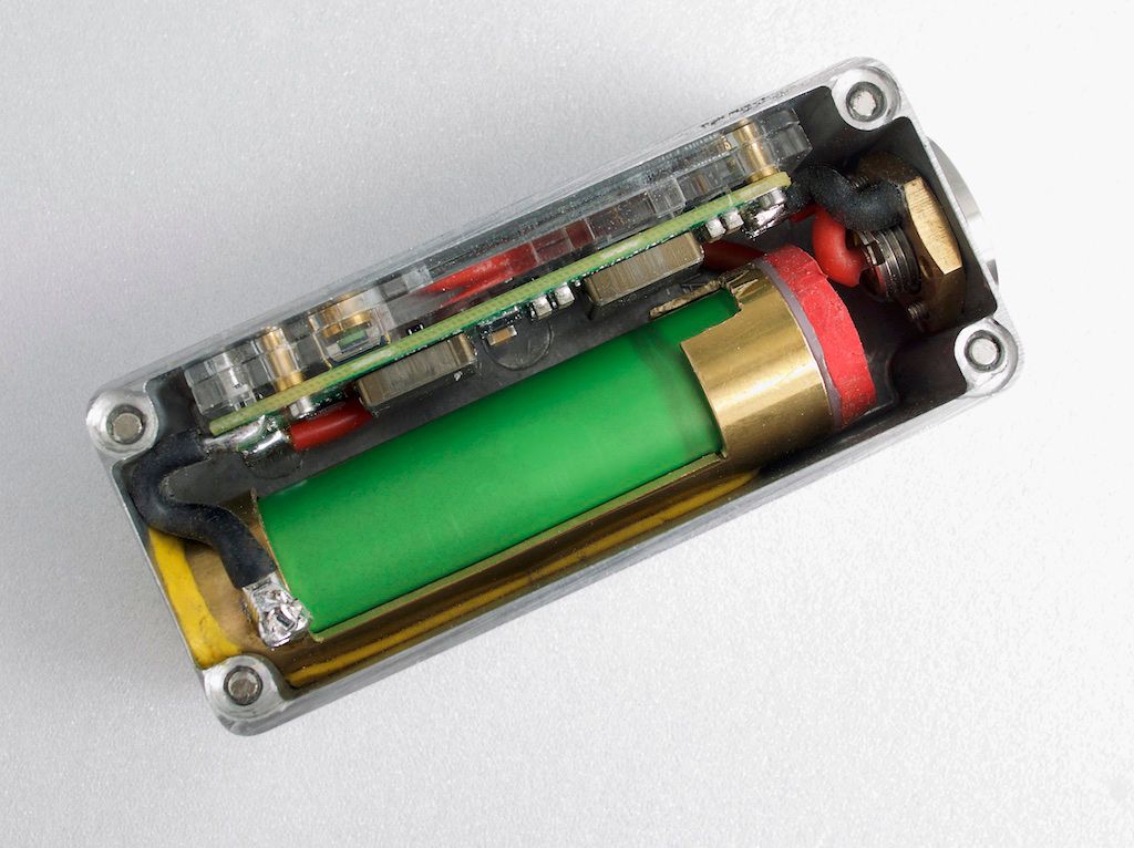
Thanks for the comments awsum140. Just depleted the first battery (VTC5) and no premature weak battery warnings. The battery showed 3.3v when put on charge.
Very pleased with the FD battery tube. -
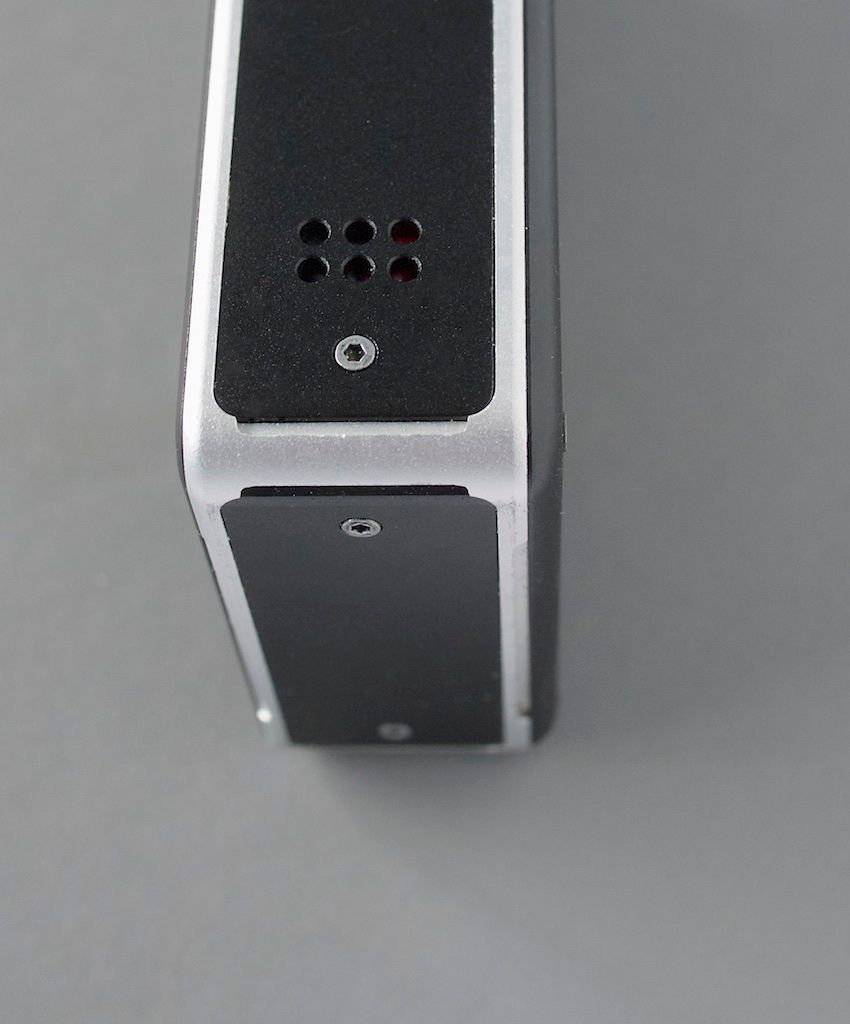
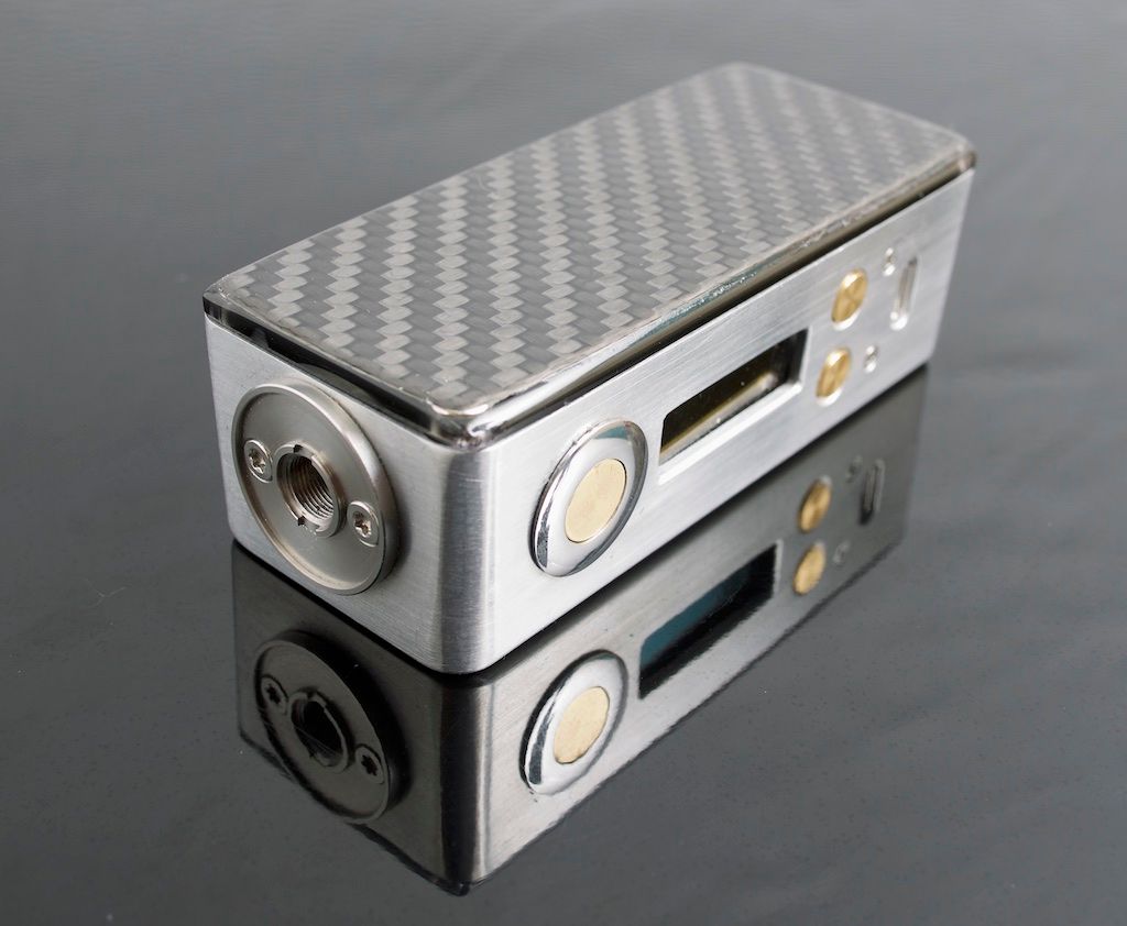
I used a hammond 1590A and mirrored a style I use for a DNA40 in the slightly smaller 1550A a while ago.
Had to change plans, made some mistakes and it's not perfect but works fine.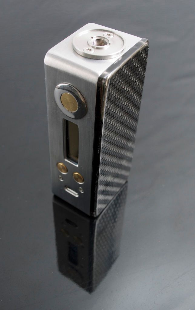
-
I've read in 'Battery University' that cylindrical batteries don't expand.
The battery is quite a loose fit in the tube diameter wise, and any slight expansion in the length, if there were any, will result in a more secure connection and be taken up by the give in the pos terminal.
Don't forget that the brass tube will expand also.
I don't think battery expansion with this setup is a issue. -
I have a Whiteout (for my sins!) and there is plenty to tinker with.
I replaced all the wiring, I don't have a pic as it was, but the output lead to the 510 wandered all round the case, had a bullet connector and was a whopping 30cms long. Not surprising that the mod resistance was halved.
I swapped out the Varitube for an Evolv and made a top plate from black perspex. Also removed the X frame and battery holder making room to change the 1100mAh for a 1300mAh and there is still room in there, the Whiteout is big!!

-
That's a good idea, could even swap it for a meatier screw.
-
It's the Fat Daddy vapes one mentioned in post 18 earlier in this thread.
The solder ring is a bit flimsy for 14 gauge and the nut only clamps it to the nylon disc. I did away with it and soldered direct to the nut
then encapsulated it in Sugru.
There was no need to slice into the tube but I felt it would give my less than dexterous hands a bit more room to work. -
Still a bit to do to finish this off, but after a lot of thought I think this is a good if not perfect solution.
-
VapingBad said:
Your wiring plan is fine scooby, short is good but no need for the power wires to be equal lengths I think the confusion comes from the balance wiring where you don't want them to vary much in resistance or it will affect the readings. I would change those battery terminals though a couple of brass pan head screws ground flat with a spring behind the negative one work well.
Cheers Jon. Wouldn't use that sled, just an illustration of what I was thinking regarding the wiring. -
awsum140 said:
I guess you'll be mounting the tube "upside down", screw cap on the top of the mod then.
Yep, slice it open so the battery can just drop in and devise a way of doing a 1/4-1/2 turn to 'lock' the battery. Just thoughts right now until it arrives and I can have a look at it.
-
ChunkyButt200 said:
looks good to me. i have to ask, is there something preventing you from running a proper gnd wire to the correct pad or you're just experimenting? please post back with your results.
Well I just looked at the layout and thought - battery at the top, + battery at bottom so what's the neatest way to run the wires.
Late last night my thoughts turned to a modified FD brass battery tube, in which case both wires will be from the bottom, the shortest path and of equal length so will satisfy my desire for neatness")
-
ChunkyButt200 said:
the output gnd and battery gnd are interconnected. so it shouldn't make a difference which pad the battery neg is soldered to. the battery neg is not being soldered to the box. what hotcig did and what this person is trying to do are two different things. 510 gnd stability is not in question, an alternative to where to solder the batt neg is. he wants to ADD the batt neg to his 510 gnd wire going to the board.
That's right. Here's a pic of what I'm planing. There's no reliance on the enclosure although the 2 screws do clamp the retaining/solder ring to secure the connector to it. (sled is just to indicate what I plan, not the one I'm using)
Normally the wire path would be down to the bottom of the enclosure to the B- pad, this way is a much shorter path.
It's been interesting reading this thread, not that I totally understand it all, thanks.
-
BillW50 said:
@scooby: It is worth a shot and it should work, but if there is a problem you will find out. It is definitely worth a shot.
Thanks for that. All in the planning stage atm and plans seem to evolve as I gather the hardware, good to know it's probably ok. -
Thanks for the comments guys.
To clarify I plan using the Cisco 510, the brass solder/capture ring has six holes, I plan on using 2 of them, one for the battery neg wire and one for the connection to ground pad. Heavy gauge wire will be used.
Although the enclosure is aluminium it's the ring that makes the connection. As I said I will still make sure the board is grounded via the 3 mounting lugs. -
As the board has common ground am I correct in thinking I can connect the battery neg to the 510 and then on to the ground pad rather than going to the B-?
I won't be relying on the enclosure as a part of the path, there will be continuity between the battery neg and the ground pad. I'll still be grounding the board via the mounting lugs. -
Wave spring? Proven to have greater spring rate than coil springs.
If Oscar Pistorius was a high jumper he'd use wave sprung prosthesis -
I've been using a Wotofo Serpent for a week or so now and it works well with temp limiting, a nice single coil tank with good flavour. The over drilled post holes and grub screws need sorting otherwise they make excellent guillotines! When will they learn?
I had the black version but exchanged it for SS as the resistance was very unstable. I couldn't work out exactly why but assume it to be the black finish.
I have a number of Squape(R)s and with the 'B' deck it's a very flavourful atty. Adjustable pos pin screw thread connection need a simple fix to give stable resistance though.
Up there with the Squape is the UTA2, that also needs the post holes and grub screw fix, It is a clone though.
I have an Aromamiser but don't use it much, maybe it doesn't suit my style of vaping as well as the others.


Common ground
in Installation and Assembly
Posted
Yep, can confirm it works perfectly.